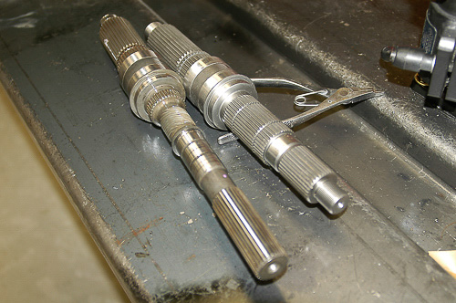
26: Stock Jeep 231 output shaft (left) is still in good condition. This NV231 transfer case is undergoing a conversion to a shorter output shaft (right) with a fixed yoke output flange. The Advance Adapters kit for the Jeep NP231 or NV231 is thorough, consisting of a new output shaft, shorter housing and all hardware needed.
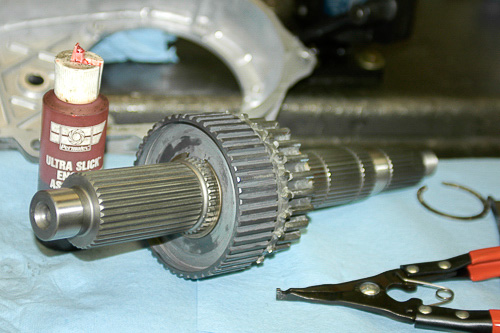
27: Assembly lube protects parts during initial start up and eases assembly. Here, mode hub and drive sprocket mount on the new output shaft, with a new snap ring installed.
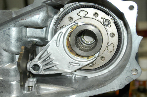
28: There is no need to remove the planetary system unless you are completely rebuilding the unit. Here, the range fork and hub are in position, showing the relationship of parts. Make sure the fork engages the shift sector slot and stays in that position during assembly! Installing the mode fork and its rail (see #29) will help keep the range fork in alignment.
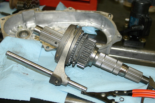
29: This is the correct relationship of parts on a clean, assembled new mainshaft. Note the direction of the mode hub sleeve. Make sure all nylon fork slippers are intact and engaged with the mode shift sleeve. The mode fork must seat in the hub sleeve groove.
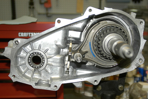
30: The output shaft in place, note the relationship of these parts. Lube moving pieces and align them without force. Keep the output shaft and the shift rail on center, aligned with bearings, splines and case bores.

31: The chain and front output shaft with sprocket go into the case together. Aligning the output shafts and carefully fitting the chain make the outer case installation possible. Fit the front output shaft into its bearing. Do not force these parts together. When you install the U-joint yoke, it will seat the shaft against the bearing’s collar.
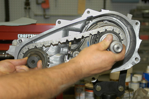
32: Aligning the outer end of the output shaft will remove chain slack. Note: Without the rear case half installed, there is slack in the chain. This is normal. If you suspect chain wear, compare the chain’s length with a new one.
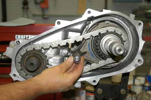
33: Center up the shift rail. Make sure that the fork engages the shift sleeve properly. These parts must remain in position as the rear case half goes into place. The mode fork spring (shown) goes outboard of the mode fork. Be sure to install this spring and keep it in place during assembly of the rear case.
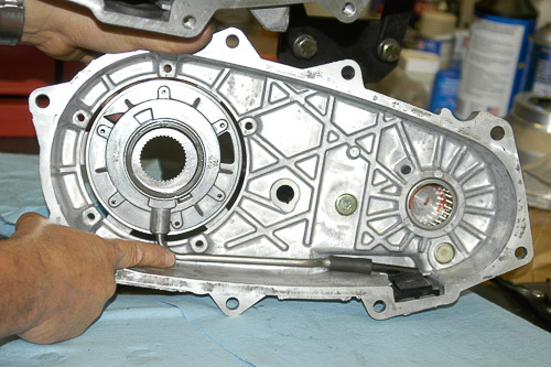
34: Make certain that the oil filter and tube align correctly. This tube must be in place or the pump will not pick up oil. Use care and make sure the tube, pump inlet O-ring, hose and filter align in their factory positions before the case halves go together.
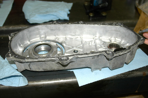
35: Use Jeep recommended Mopar RTV or a high-quality equivalent. I run a uniform, 1/8” wide bead of sealant around the rear case half. Circle the bolt holes, and stay in the center of the machined surface. Since the halves are precisely machined, the mating faces will squeeze sealant over the surface. Excess sealant is unnecessary. However, make sure there are no sealant gaps that could leak.
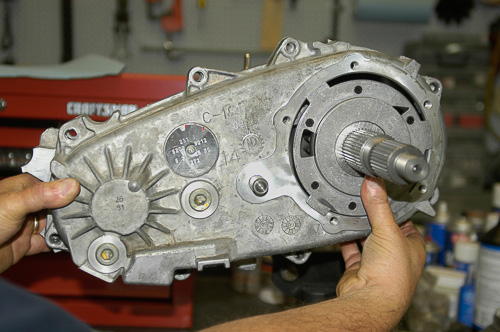
36: The pump and case halves go in place together. Keep the pump in position to assure proper oil tube engagement. Center the cases to prevent smearing sealant as you bring the case halves into alignment. Use the dowels as a guide, and keep case faces parallel. The mode fork rail must fit properly through the rear case bore. All parts should align as you bring the halves together evenly and snugly. I use Loctite 242 (blue) on bolt threads and finger-tighten the two dowel bolts to keep the case halves aligned.
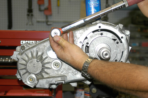
37: Bring all bolts up evenly. I use a speed handle for this chore. Tighten in cross, a few threads at a time to keep the case halves parallel and prevent binding of any internal parts. Watch the oil pump to be sure it stays engaged in the oil tube. With all bolts snug, final tightening is with a torque wrench. Recheck torque after parts set for a few minutes.
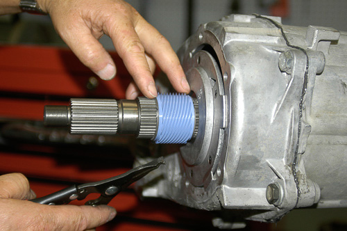
38: Install the Advance Adapters speedometer drive (speed sensor) sleeve with its snap rings. The stock output shaft has speedometer drive teeth cut into the shaft. The nylon sleeve approach works nicely and provides a serviceable part. The sleeve has inner splines for indexing.
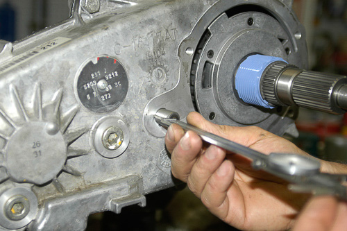
39: Case halves securely tightened together, the shift rail gets checked for stickout height. The new retainer/output shaft housing will go into place next.
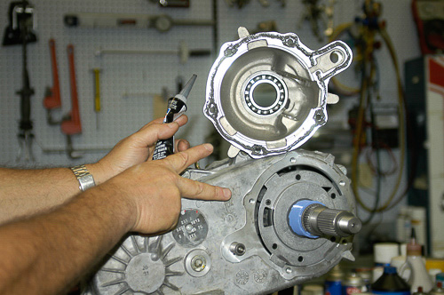
Note: Final torque specifications are in the Advance Adapters instructions. At the end of this section, I have included the Jeep factory torque recommendations for the NV231.
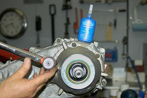
41: Final tightening is in cross and with a torque wrench. Bring retainer flushly to the case. Tighten gradually to prevent binding. After parts set for several minutes, I check torque once more, in cross and sequence.
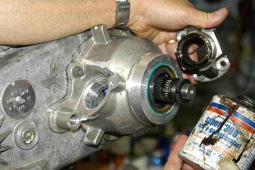
42: New retainer housing in place, I install the 32-spline output yoke supplied by Advance Adapters. Brush a thin, even film of Super 300 or similar sealant on the inner spline threads. Also coat the machined inner seat of the yoke (as shown). These added steps prevent oil from seeping between the shaft splines and yoke. Note the new rubber seal that fits between the shaft threads and yoke nut.

43: New yoke is now in place. Sealant on splines and a new rubber yoke seal (provided by Advance Adapters) assure leak-free service. Loctite 271 (red) is additional insurance, used with a new, self-locking pinion flange nut. On hard steel assemblies and threads, Loctite 271 acts as a thread locker and additional sealer.

44: Although I have the Jeep-recommended flange holding tool, this is an alternative that works. I protect the yoke flange with a rag and hold the outer yoke while tightening with a large torque wrench. Initial tightening is with an air gun, set to below the final torque recommended.

45: This is the Jeep-recommended tool for holding the U-joint flange. Final torque is with a large torque wrench. Make certain that yoke flanges have been properly sealed and torqued to specification. Once done properly, these yokes will not need further attention. Each output yoke will now accept a CV-type driveline assembly. The new Advance Adapters rear yoke flange accepts the popular 1310 size Spicer CV joint.
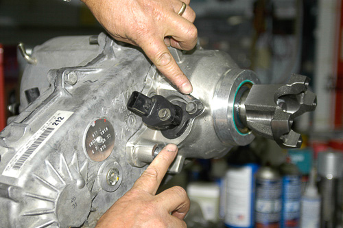
46: I clean the outside of the speedometer housing with a rag and alcohol. Coat the O-ring lightly with RTV sealant as recommended in the Advance Adapters instructions. This unit fits the new tailhousing/retainer perfectly. The original alignment marks will also work here, as the clamp bolt locates just like the original, 1999 XJ housing.
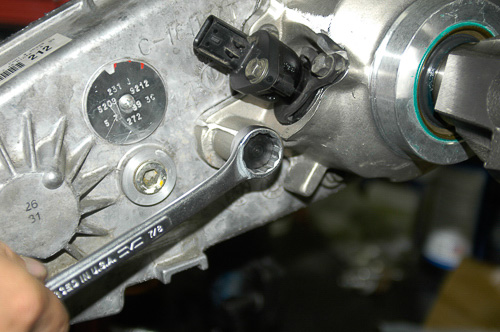
47: Here, I install the mode rail bore’s end plug and gasket supplied. Secure this plug to assure a leak-free seal. A thin film of RTV sealant helps.
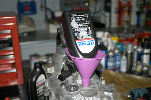
48: Before installing the transfer case assembly, I fill the unit to specified capacity with Mopar’s Dexron-III/Mercon ATF. At that point, I seal the vent tube temporarily with a vacuum cap and rotate the transfer case assembly slowly in all directions. This checks for leaks and also coats all parts with ATF. Remove vacuum cap before installing vent hose.

49: NV231 transfer case now boasts an Advance Adapters ‘SYE’ kit upgrade! The unit will perform better than new. The NP/NV231 is not complicated, and if rebuilt properly, it can be a very reliable unit. There are aftermarket, lower range gear sets available for these units. The stock ratio is 2.72:1 in low range, 1:1 in high range.
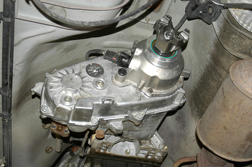
50: The NV231 transfer case is now back in the chassis! The unit is ready for a CV-type rear driveline, just part of the 6-inch, long-arm suspension lift upgrade to this 1999 XJ Cherokee. This 231 transfer case, with a 4.0L inline six, 4.10:1 gears, ARB Air Lockers front and rear, and 33″ diameter tires, will handle some rough terrain!

Jeep® “factory” torque/tightening specifications for the NV231 transfer case. (Specs are similar for the NP231.) For the output yoke nut and other ‘SYE’ related tightening specifications, refer to the guidelines furnished with the Advance Adapters ‘SYE’ Fixed Yoke Kit.
