The installation of a Jeep TJ Wrangler Full-Traction Suspension 4” Ultimate package provides guidelines for front suspension rebuilding and even a complete axle housing replacement. Whether you intend to lift a TJ Wrangler, repair a damaged front end or replace worn components, this article provides step-by-step procedures and insight for any TJ front end and suspension work.
Front Suspension Work
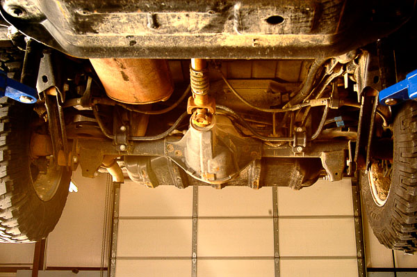
Illus. 5: This angle shows the factory four-link suspension used with a beam axle. Four-link technology for the front beam axle began with the XJ Cherokee chassis. Rear of the TJ resembles the ZJ Grand Cherokee, especially with the Rubicon Edition’s disc brakes. Add a ladder frame with stiff modular sections, and the TJ Wrangler delivers exceptional performance while remaining relatively easy to service.

Illus. 6: Upper and lower control arms with coil springs provide excellent control and axle arcs of movement. Use of a track bar for lateral stability plus a rear sway bar to help temper body roll on turns, the TJ is a road-worthy vehicle. The TJ boasts some of the best automotive suspension technology without compromising off-highway prowess. A stiff frame allows for precise tuning of the link-and-coil suspension. A hefty front stabilizer helps the chassis squat more squarely on turns and lowers the center-of-gravity.
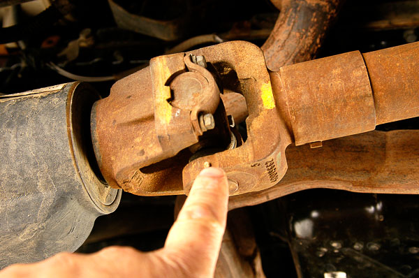
Illus. 7: Rubicon models boast a 1330 size U-joint package. The rear driveline is not the typical slip yoke found on all YJs and the other TJ models. Rear driveline uses a splined slip-collar much like trucks and Jeep 4x4s of the rugged utility era. Standard U-joints on YJ and non-Rubicon TJ models are durable 1310 Spicer size. Strap and bolt attachment (shown) is typical of contemporary vehicles. Note the factory alignment marks indicating the balancing position. Always restore parts to these positions.

Illus. 8: Newer recirculating ball-and-piston rack power steering boxes are still integral power type with a sector and pitman arm. New design is serviceable but requires different approaches than the traditional Saginaw gears. This later gear is easy to identify by its cast nose without a removable cup end and lock ring. Equal durability is assured. Saginaw integral power steering gears have an excellent reputation among U.S. auto and truck builders.
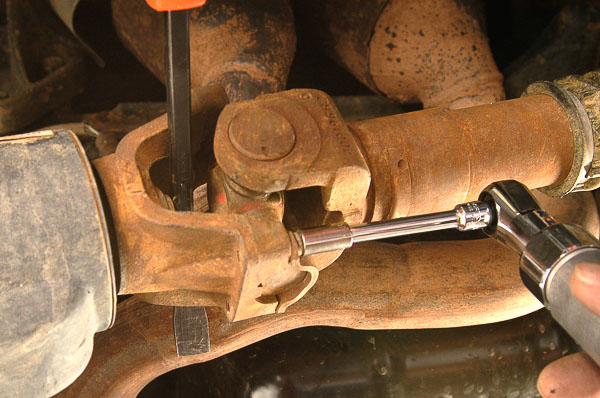
Illus. 9: This suspension revamp begins with removal of the front driveline for easier access to the suspension and axle assembly. As the front shaft will be reused, some installers leave the shaft in place. Note my use of an air ratchet and a six-point socket. These tiny bolt heads are easy to round, which can create havoc. Stay squarely on the bolt head while loosening.
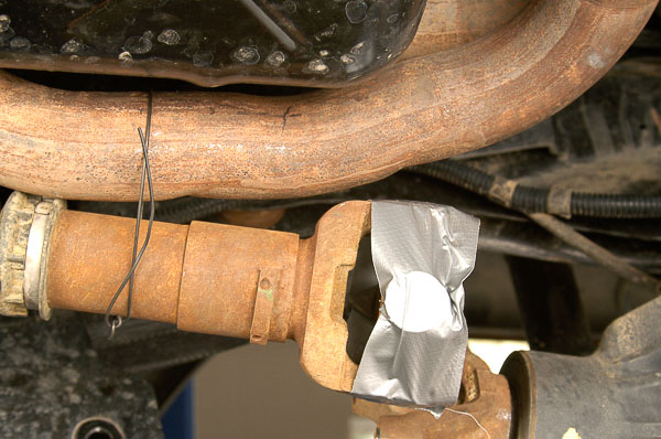
Illus. 10: I immediately duct tape the bearing caps in place to prevent caps from dislodging. These are “permanently sealed” U-joints and will go back in place without an issue. I tie the driveline safely out of the way with mechanic’s wire. Never allow the driveshaft to hang! This can damage U-joints and seals.
Caution: When prying the U-joint from the yoke saddles or holding the joint yoke, use care not to damage the bearing seals on the U-joints! Know where the seals ride on the caps. Keep your pry tool away from the sensitive seals. Avoid damaging expensive parts that can otherwise be reused. U-joints on this TJ Rubicon have only 6,000 miles of wear.
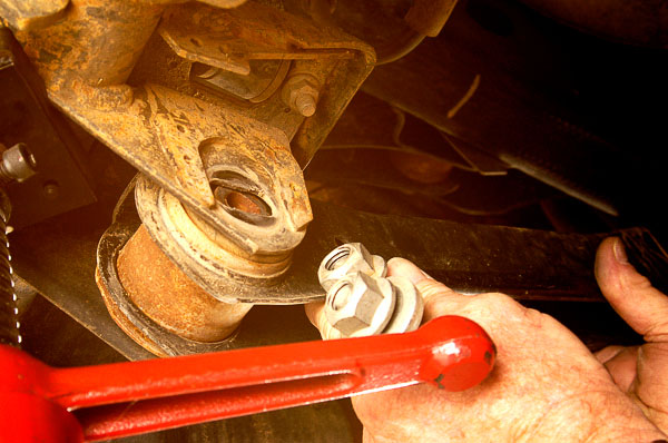
Illus. 11: For better parts access, I remove the bolts for the left lower control arm. These bolts will go back into place shortly to prevent the axle housing from rotating. If not in the way, leave this arm in place for now. On many TJs, these forward bolts have eccentric heads that adjust and hold axle caster position. If this were a simple replacement of a damaged control arm, mark the eccentric’s location to quickly reset caster at its proper position.
Note: At right and left side lower control arms, the front axle caster can be adjusted. Since this is a beam axle, each side must be loose for adjustment of caster. (Later TJs have factory pre-set caster determined by fixed bracket locations.) These forward bolts have a round alignment washer as shown on this 2004 Rubicon. When there is a need for service adjustment of the caster angle on this model, a factory “kit” is available with bolts that have eccentric heads—essentially those found on earlier TJs!
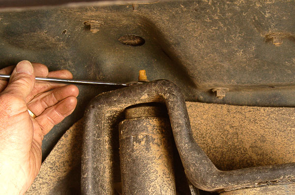
Illus. 12: You can readily remove the shock absorbers on a TJ, however, beware! These shocks serve as the suspension drop stops for chassis movement. With the shocks removed, front or rear coil springs can readily come loose. Unload spring and shock absorber pressure by carefully lowering the axle housing to the full drop of the shock absorbers. At this point, continue to support the axle housing as you remove the shock absorbers. Do not allow a spring to come loose. Do not unbolt a loaded, gas-charged shock absorber.
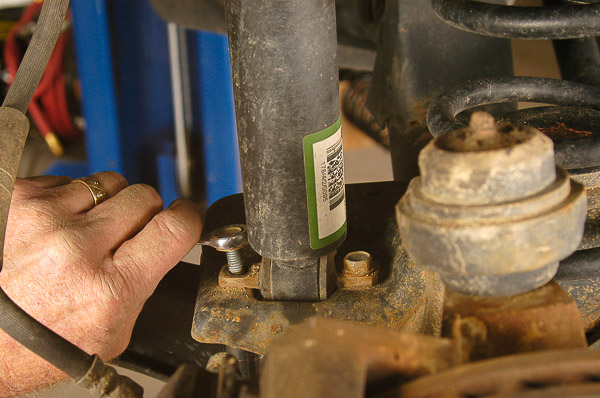
Illus. 13: Make sure the shock absorber is fully extended if gas-charged type! Continue to support the axle housing while detaching the shock absorber. Shock replacement is simple enough—if you follow safety precautions! If replacing the shock absorbers, match length and travel to assure that the shock absorbers will not restrict suspension movement over the normal range of suspension cycling and travel.
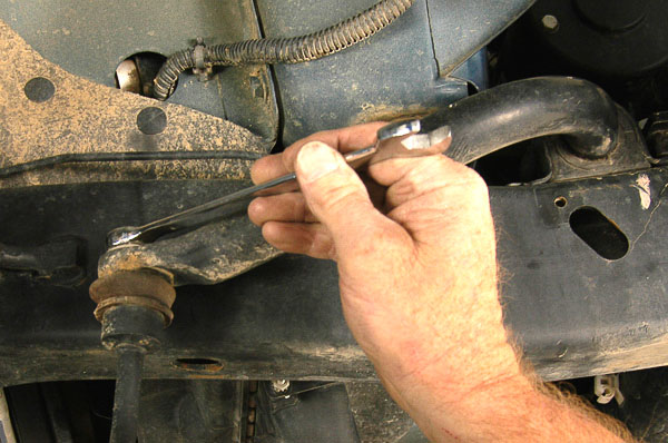
Illus. 14: Loosen stabilizer link from the bar. The lift kit will include custom stabilizer links. They will be longer, to accommodate the 4-inch chassis lift.

Illus. 15: Torx hardware is common on Jeep vehicles. Since the 1980s, this hardware has become popular for quick assembly and disassembly. Always use the correct Torx bits and drivers to prevent damaging bolt heads. A stripped Torx head presents a serious problem. Purchase a quality Torx bit set if you perform Jeep work. Inexpensive tools will twist, strip and break.
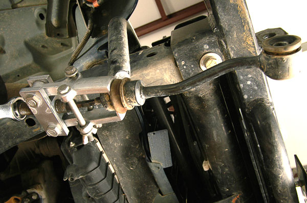
Illus. 16: A puller with protection for the stud threads will quickly dislodge the link from the stabilizer bar. Do not attempt to beat or force this part loose. The puller assures that you can reinstall the parts if required. This Jeep being nearly new, these links are in good condition. I carefully push away and protect the boot seal to prevent the puller jaws from causing damage.
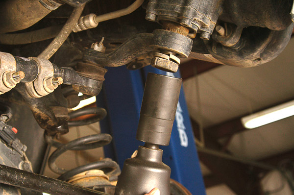
Illus. 17: I loosen the pitman nut the easy way—with air impact force. Always move the pitman arm to the center of its travel before applying pressure to the nut. If you must loosen this nut by hand (like alongside a trail), center the arm midway between left and right turn extremes. Hold the arm in this position with a large pipe wrench. Use a rag to protect the arm from the wrench jaws. This nut has a high torque setting. Be careful.
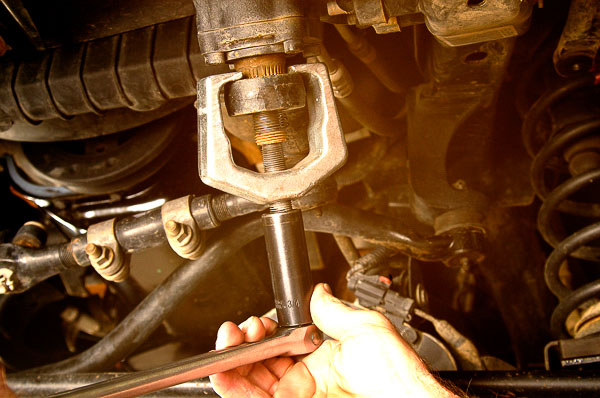
Illus. 18: Note my use of a pitman arm puller for removing the pitman arm. Use no other tool. Do not pry the arm loose, as severe damage to the steering gear can result. I use anti-seize compound on the puller threads and hold the pitman arm in its center position. Forcing the steering gear’s sector shaft to left or right extremes can severely damage the ball nut/piston rack, ball bearings and the wormshaft. Support the puller while rotating the stem. The fit can be very tight at the tapered splines of the sector shaft.

Illus. 19: Here I have chosen to leave the tie-rod end attached to the pitman arm during removal. I remove the cotter pin and use an air impact gun to quickly loosen the tie-rod/draglink end nut. Air tools can lessen risk of parts damage and physical injury if used properly. Protect your eyes and ears when using air tools.
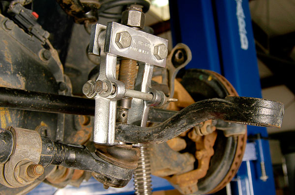
Illus. 20: Now I use a tie-rod puller to remove the tie-rod from the tapered seat of the pitman arm. Force, again, can be high. Use the right tool to prevent damage to the tapered ball stud. If you plan to reuse this joint, protect the threads and the end of the stud. The design places the cotter pin hole close to the stud end. The cotter pin hole can collapse from too much pressure on the stud end.

Illus. 21: The track bar will be replaced during this suspension system installation. Here, I am loosening the track bar at the axle housing bracket. The axle is supported on stands to prevent abrupt drop when the bar comes loose. On adjustable stands, the axle height and position is easier to maintain or change as necessary. Avoid parts binding. Use caution when loosening components from the weighty axle assembly. Do not get pinned to the floor by the axle assembly!
Warning—Axle assemblies can be wieldy and hefty. Plan ahead when detaching parts. Use safe stands and straps to prevent problems. Keep parts from rotating and falling. When possible, disassemble and assemble one side of the axle at a time to maintain control of these heavy assemblies. This article illustrates some of the ways to support and maintain control of an axle assembly during this work. Be cautious. If components are too heavy to handle, use jacks, stands and a strong helper.
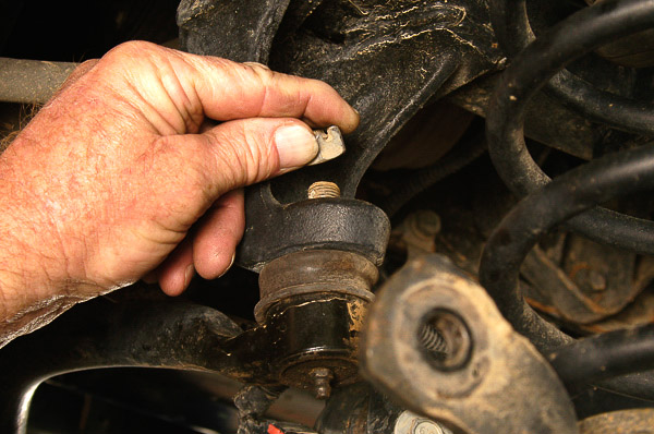
Illus. 22: Taller suspension lift kits require relocation of the track bar. This Full-Traction Suspension package includes a new track bar designed for the arc of travel on the dropped axle. A unique bracket will support the frame end of the new, adjustable track bar. Here, the factory nut is loosened to allow removal of the original track bar.
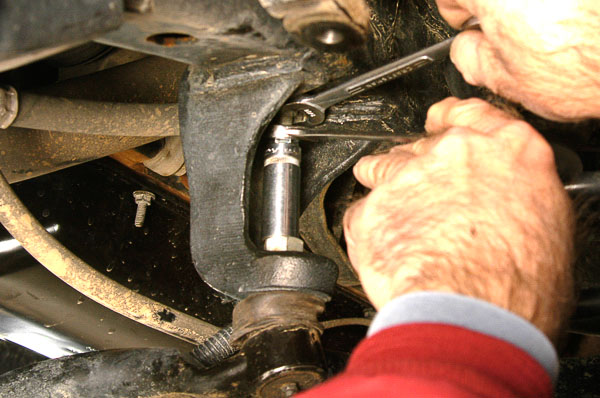
Illus. 23: There is no room to get a puller into the space above the track bar ball stud. Here, I make a simple spreader tool to press the tapered ball stud from the frame mount. The stud is much like a tie-rod design. A nut protects the threads and provides a seat for the socket “press” tool. A length of rod stock and two nuts serve as the spreading device. In Illus. 24, you will see the parts that quickly pushed the tapered stud from its seat.

Illus. 24: These simple pieces make up the spreader tool. I welded a nut to the top of the stud. This keeps the stud from rotating as I tighten the lower nut against the deep socket. As the socket presses downward against the nut at the ball stud, the stud is forced out of its taper. The upper end of the tool fits against the hood of the cast bracket. (I prefer not whacking on the casting flange to loosen the stud!)
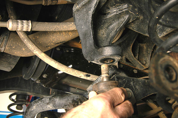
Illus. 25: The track bar is loose at the pivot end. Opposite end at the axle has a bushing and bolt attachment. With that bolt loose, the track bar assembly can be removed from the chassis. This procedure is the same whether you change the track bar or replace a damaged unit. The joint should be protected if you intend to reinstall the unit. A new track bar assembly is expensive.
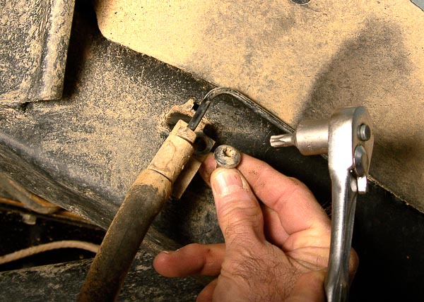
Illus. 26: When installing a lift kit, the brake pipes and hoses need attention. This suspension system includes drop brackets to relocate the brake pipes and original hoses. Some kits require an actual change to longer brake hoses, typically stainless steel braided type. Always make certain that there is adequate brake hose clearance for the new suspension and axle locations. Consider the front and rear axle braking systems. Here, I loosen the brake hose brackets before lowering the front axle.
Important Notes: Suspension Lifts and Brake Safety Issues
Wrangler owners personalize their vehicles in many ways. Choices in recovery equipment, stowage racks, suspension products, tires, wheels and chassis components make these vehicles unique. For this reason, suspension system and lift kit installations require close attention to details. You will find notes and footnotes in the manufacturer’s installation instructions. There are also some general concerns that you should always consider. Among these concerns are brake hoses and brake lines.
Changes to the chassis, wheel/tire size changes and other modifications may affect brake components. The goal is to always maintain a safe brake system, consistent with original equipment engineering standards. Consider these points when installing a suspension lift kit or system:
*Whenever you install a lift kit of any kind, always check for sufficient brake hose clearance. Due to the varieties of springs, sway bar disconnects, axle layouts, wheel/tire combinations and chassis differences over model years, the brake hose lengths may need changing.
*Check brake hose length with the axle in full drop position. If you have sway bar disconnects, unhook disconnect links to increase drop. Allow for axle flex and articulation, which will increase the distance between the brake calipers or axle and the frame brake pipes. Turn the front wheels full left-to-right and observe the brake hose clearance.
*If the hoses are stressed or stretching to any degree, you need to install longer brake hoses. Braided steel hoses are available. OEM replacement hoses of similar design and fittings may be available through a local brake parts supplier or auto parts retailer. Savvy parts counter staff can often find longer length, OEM quality hoses of the same design and fittings as your Wrangler’s hoses.
*When installing longer hoses, make sure that they do not interfere with moving parts as the axle moves through its range of travel. Check the hoses at full drop. Take into consideration the full upward travel of the axles. Turn the front wheels left and right to extremes, observing hose clearance throughout the wheel turns. Be certain that the hoses will not rub or chafe against chassis parts, wheels/tires or steering linkage.
*Tighten the brake fittings properly to avoid fluid leaks. Fabricate brackets, if necessary, to position and support hoses out of harm’s way. Always bleed the brake system after installing hoses. Make sure the front and rear brakes work properly!
Brakes are a critical safety concern. When installing a lift of any kind, check for clearance and safe routing of brake hoses and brake lines at the front and rear axles, along the frame and to each brake cylinder and caliper—before driving your vehicle. Sometimes, the fix is as simple as installing the brake line drop brackets supplied with a suspension package. In other cases, new and longer brake hoses may be necessary. If you relocate or move any brake pipes, be certain that they route safely, away from rough edges or interference with other chassis parts. Visualize the movement and ways that parts may become damaged. Protect your Jeep’s brake system!
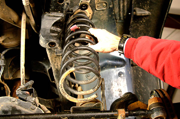
Illus. 27: Keep the link arms attached. With the shock absorber removed and the axle supported on jacks or tripod stands, lower the axle assembly at the driver’s (left) side. Drop the assembly slowly to unload any spring tension. You may need to lower both sides to unload the spring tension fully. Keep the suspension and axle aligned and the springs under control at all times! Once the springs are unloaded and loose, simply remove the coil assembly.
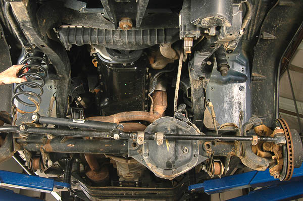
Illus. 28: Link arms still attached as shown, the spring tension is fully unloaded. The right spring lifts readily out of place with the axle dropped to this point. Drop of the axle is not restricted, as the shock absorbers and stabilizer link arms have been removed. TJ springs do not use clamps and simply fit onto the spring pads. (Axle installed to its normal position with the shocks in place, the new Full-Traction Suspension lift springs will stay in position.) Front spring lower ends fit against the spring pad’s recessed stop.
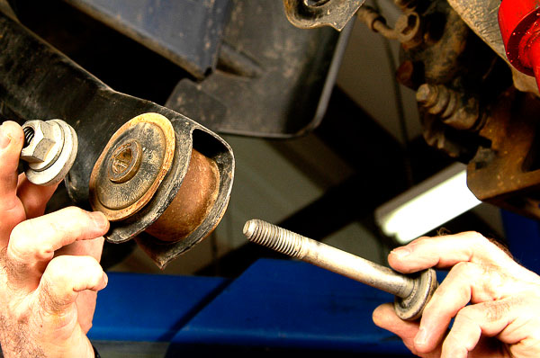
Illus. 29: I place stands beneath the axle housing and keep the frame in a fixed position. This is easier to do with a vehicle hoist and a pair of adjustable tripod stands rated one-ton each. If necessary, improvise with quality floor jack stands, frame stands and sturdy floor jacks. Maintaining axle alignment will make installation of the link arms easier and hold chassis alignment during assembly. Now, with the axle supported, the lower link arms can be removed. Shown is the left side, its forward hardware loosened.

Illus. 30: Here, the left lower control arm’s rear hardware is loose. The arm should slide out readily. Make certain that the axle housing is safely supported. Prevent the housing from rolling off the support stands. I move to the right lower control arm.
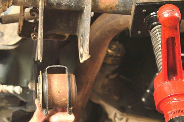
Illus. 31: Right side lower control arm comes loose now. This is the front bolt and nut. Some kits will require reuse of OE hardware; others provide new hardware. Follow the kit’s instructions. If repairing or replacing OE hardware with like kind, remove hardware carefully and note its location and the position of the bolt and nut.
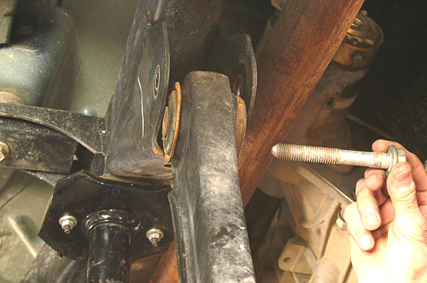
Illus. 32: Remove the rear hardware from the left lower control arm. At this stage, the axle housing can roll or drop. Use care to prevent this from happening. I will place a third stand beneath the axle pinion snout. If necessary, strap the housing to prevent it from rolling or sliding from the support stands. (See Illus. 39 for three-stand support details.)

Illus. 33: Upper control arms and driveline help keep the axle housing from rotating at this stage. A stand sets at each side of the axle housing. For alignment and assembly ease, keep these parts centered and stable on the stands. Many TJ suspension kits have adjustable link arms. Alignment is much easier if the original axle/frame positions are clear during assembly.
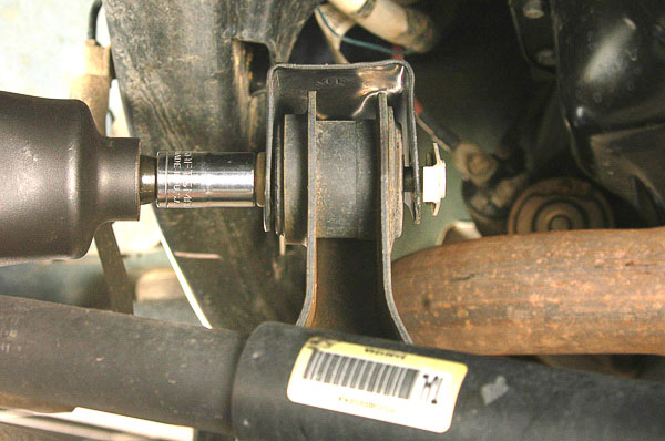
Illus. 34: Now I remove the upper link arms—carefully, one at a time. Watch for axle housing movement. Keep the parts aligned. As the second upper link arm loosens, the axle will want to rotate. The attached driveline may prevent some rotation. Stands will keep heavy parts from dropping.
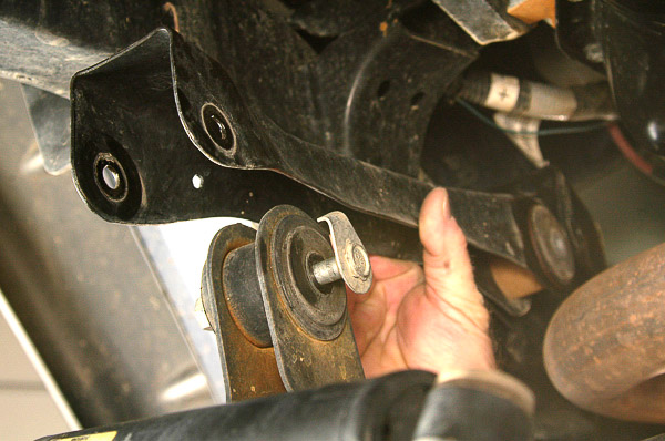
Illus. 35: Here I lift the right side upper control arm free. The left upper link keeps the axle from rotating at this point—if the stands support the axle housing properly. This is a heavy axle with the brake hoses and driveline attached at this stage. Do not hyperextend or damage any of these parts. Keep the axle housing and frame stable.

Illus. 36: There are many reasons why a suspension lift is considered valuable. The suspension height increase will provide more ground clearance and room for oversized tires when desired. Trail tuned springs and shock absorbers appeal to many backcountry users. With some packages, components may also be upgraded substantially as illustrated in this comparison of a Full-Traction Suspension TJ control arm (bottom) with the original arm. FTS urethane bushings and swivel joints provide superior control and movement while eliminating arm and bushing bind.
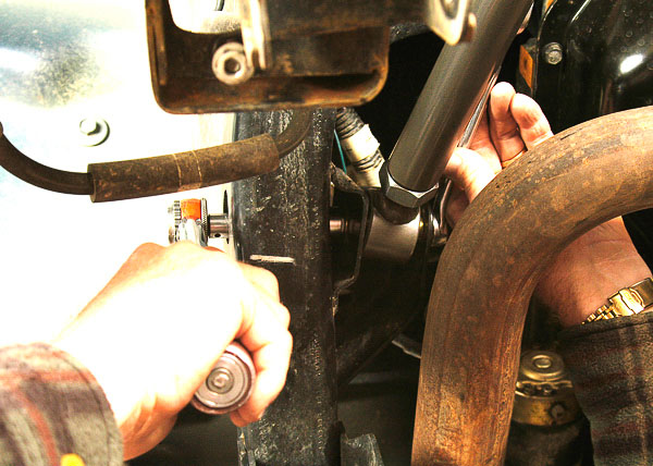
Illus. 37: I install this new right upper link arm before removing the original arm at the left side of this axle. By doing so, the axle remains supported by at least one link arm at all times. This link arm requires adjustment to bring axle alignment and caster into specification. Follow the manufacturer’s instructions to set preliminary length adjustments on these link arms. A four-wheel alignment shop can later confirm squareness and alignment of the front and rear axles with the frame.

Illus. 38: Use Loctite 242 on threads. New hardware furnished with this suspension system employs top-lock (all steel) Grade 8 self locking nuts. Once torqued to specification, these parts are ready for a long service life. Full-Traction Suspension provides grease fittings for periodic lubrication of key joints. Swivel joints are high-quality, rugged components designed for longevity. At this position, the non-greaseable OE bushing is retained.

Illus. 39: New right side upper control arm is in place. Original upper left arm is still attached. Three stands beneath the housing prevent axle drop and rotation. Note that the third stand sets beneath the snout of the axle pinion section. This takes the load off the driveline and keeps the housing from swinging downward. By using care to support the axle and frame, I maintain alignment and keep the chassis/axle relationship square.
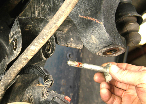
Illus. 40: Axle supported, I detach the front hardware of the left upper control arm. At the axle end, the original bushings will be reused. FTS suspension system uses OE components where practical and suited. OE hardware often has a special use and function. If you are simply replacing OE control arms, always use OE type hardware in the way intended. This specialized hardware is metric on later model Jeep vehicles.
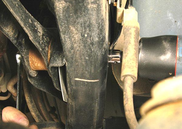
Illus. 41: Support in place, I loosen the rear hardware on the upper left control arm link. Here, air tools can speed up the process. Note the hardware location and positions if you intend to reinstall OE type components. By attaching the opposite upper arm first, there is less risk of the axle shifting from position or placing undo load on the hardware.

Illus. 42: These upper arm bolts in the FTS package have grease fittings. Special bolts have a drilled center for the grease passageway. When installing these kinds of bolts, observe the torque setting from the manufacturer. Due to the passageway, the torque setting is much lower than the OE specifications. Follow the suspension system manufacturer’s recommendation.

Illus. 43: Here, the front link arm bolt is OE type. When reusing any hardware, make sure self-locking nuts will work properly. I add Loctite 242 Threadlocker to any of this hardware as a safety backup. Torque hardware to specification. The OE bushing, like the FTS urethane bushings used in this package, has an internal steel sleeve that bottoms against the shoulders of the axle bracket.
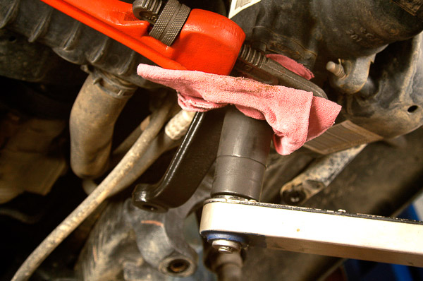
Illus. 44: I now install the dropped pitman arm supplied with the suspension package. Clean the sector shaft splines and make sure the steering gear is in the centered location. Never tighten a pitman arm nut with the arm turned to left or right extremes! Using a rag to prevent nicking the new pitman arm’s coating, I install the lock washer and nut while holding the arm with a large pipe wrench. Set the nut to specification.
Note—A dropped pitman arm is common to kits in the 2”-4” lift range. Beyond these lift heights, relocation of the steering arms or a special steering system like the FTS “K-Link®” design will be necessary. The dropped pitman arm lowers the draglink/short tie-rod height to help restore the draglink angle and prevent bump steer with the lifted, additional chassis-to-axle spacing.
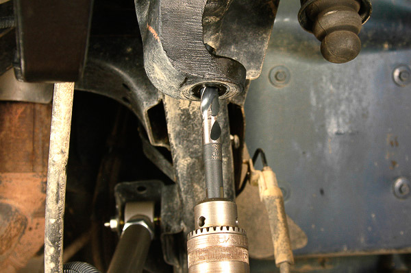
Illus. 45: The FTS 4” Ultimate lift package is described as a “bolt-on” suspension system. Minor drilling should be expected with this kind of package. Here, as the instructions note, I ream out the track bar bracket’s tapered seat slightly to accommodate the new drop bracket for the track bar. Slight reaming at small end of the tapered bore matches the hardware that holds the drop bracket in place.

Illus. 46: This custom bracket (left) lowers the pivot point for a new track bar found in the FTS package. Smart use of OE attachment points makes this a bolt-on approach. The new track bar is a rugged, adjustable piece. On a Quadra-Coil suspension system, the track bar is a critical component. This bar keeps the axle in lateral alignment. When lifting a link-and-coil system, the track bar must be of correct length and shape to maintain the proper arc of axle travel. Here, I torque new hardware in place.
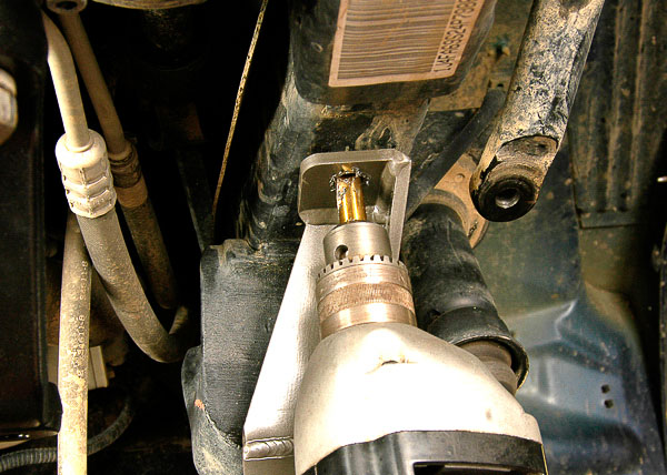
Illus. 47: Another helpful approach is the FTS use of an existing frame hole as the centering point for the drop bracket guide tube. Smart design uses the guide tube to center the drill. A hole is made through the upper frame rail, carefully avoiding the brake pipe and any other components. Hardware will fit through the guide tube, using the tube as a spacer to reinforce and back up the frame rail when tightening the hardware. This is a sound and simple approach that requires only a quick drilling step—with a sharp drill bit.
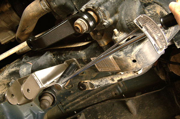
Illus. 48: Supplied, Grade 8 bolt and nut secure the guide tube to the frame. Torque the hardware to specification. When installed, this bracket will provide the dropped track bar location necessary for a 4” suspension lift. Even a mild 2” lift will affect the lateral position of the track bar and axle. The FTS approach includes an adjustable track bar end to assure precise lateral alignment of the front axle.
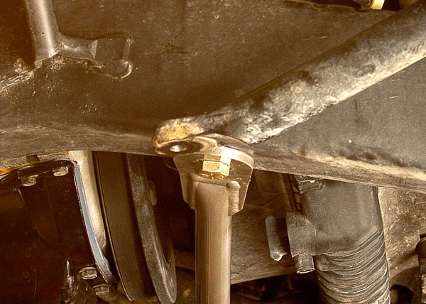
Illus. 49: The FTS track bar assembly accommodates the huge forces applied to the frame bracket/pivot point. To brace the dropped track bar bracket, the kit includes a special support rod that reaches to the right side frame rail. The factory frame hole and the brace’s guide tube serve as the drill guide. Drill through the frame, taking care not to drill through the brake pipe! There should be enough clearance, but be careful. Torque the hardware to specification.

Illus. 50: I coat bushings and internal sleeves with moly- or silicone-type grease. Urethane bushings will bind or squeak without proper lube. Some of the FTS components have grease fittings to provide periodic lubrication. Many kits do not have such provisions. Owners must periodically disassemble and lube the joints. Installed track bar shows FTS supplied hardware and the bushings in place. Torque the hardware to specification.
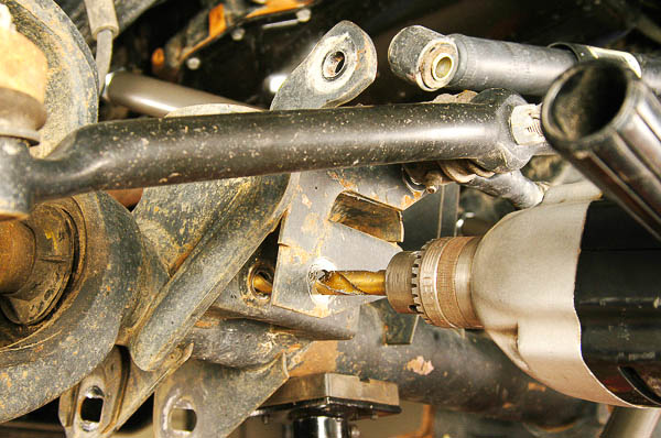
Illus. 51: FTS instructions call for reaming the axle/track bar bracket holes slightly to fit supplied hardware. This modification allows use of the heavy-duty FTS hardware at the Heim joint end of the track bar. Considerable engineering went into this package to reduce the chassis modifications. A bolt-on kit is much easier to install than those that require cutting, welding and major, irreversible modifications.
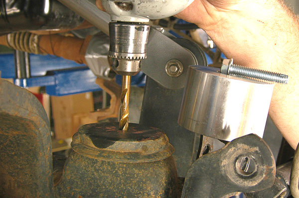
Illus. 52: Bump stops must be altered to reflect the new suspension height. The bottom stops require drilling this very hard factory bump stop plate. Bolts supplied are of self-tapping type. Many installers would be content with drilling the hole and cutting a thread with the new bolt as designed. This steel plate material is so hard that I elect to tap the drilled holes, using the thread size of the new bolt.
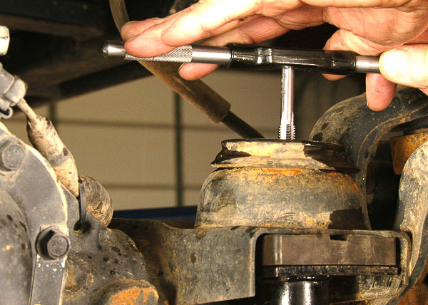
Illus. 53: Tapping the new holes, the hardness of the plate is evident. Use the tap carefully. Turn the tap a quarter to one-half turn at a time then back off the tool to clear the cut material from the cutting edges. This was not a quick task. You do not want to break a tap in steel this hard! (Good tap material is as hard as your best drill bit.) Take your time, and use cutting oil to reduce friction. Protect your tools.
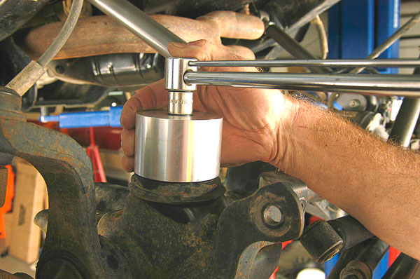
Illus. 54: The bump stop bolts go readily into place, securing the new aluminum bump stop spacer. This part is critical to suspension travel and protecting the steering linkage, driveline and link arms from hyper-extending. Using Loctite 242 on the bolt’s threads, I torque the bolt to specification.

Illus. 55: I could have swung the axle far enough down to squeeze the spring into place. Another method is to put the bump stop inside the spring, install the spring, and bolt down the bump stop from within the spring. Instead, I chose to compress the coil spring with a coil spring compressor set. Spring and bump stop in place, I can loosen the clamps evenly to expand the spring.
Note—Installers should be aware of the spring compressor option, as it enables careful ‘R&R’ (removal and replacement) of coil springs. The right tools can contribute to safety and ease parts installation.
Caution— Front spring pads have a stop edge to catch the spring end and prevent the spring from rotating. Make sure each spring’s lower end fits to the stop edge.
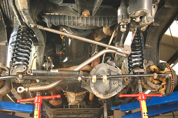
Illus. 56: Both coil springs in place, the relationship of the track bar to the frame is clear. The stabilizer shock remains disconnected to permit easier work near the steering linkage. Three tripod stands support the axle and springs. The track bar is loose at the axle attachment point. Upper control/link arms are in place. Lower arms go into place now.
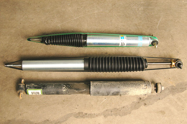
Illus. 57: Shocks dampen coil spring oscillation and double as the suspension/spring drop stops on the TJ Wrangler suspension, preventing the axle from swinging too low and allowing the springs to come loose. Three shocks shown are a Bilstein 5100 gas charged unit (top), the FTS/M-Force shock (center) and the OE TJ Wrangler shock (bottom). The M-Force and Bilstein types are fully pressurized, gas-charged shocks, tuned for precise highway handling and rugged backcountry use.
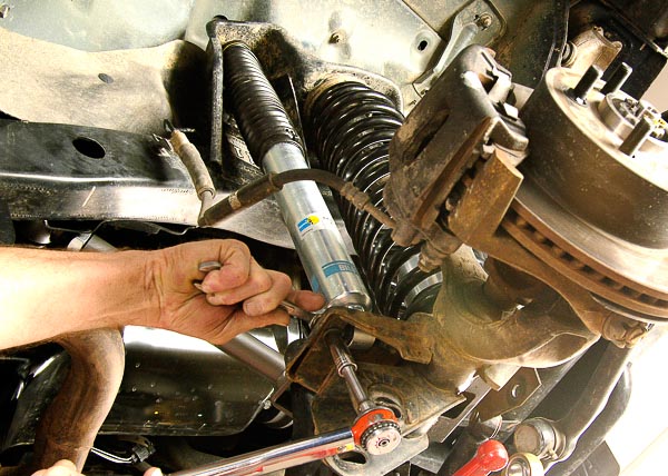
Illus. 58: With the axle housing supported and suspension/coil springs at the right height, the shock absorber fits at the OE location. Instructions and needed attachment hardware come with each shock absorber. Use OE torque specifications or those provided by the shock manufacturer. The shock in place, coil spring force will not hyper-extend the axle. Keep the support stands in place at this stage.
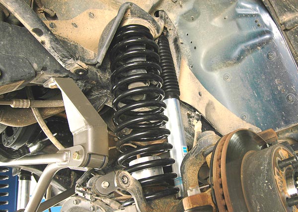
Illus. 59: Left shock assembly in place, the relationship of the spring and axle position is clear. Support stands will remain in place until the lower link arms are fully installed. Steps shown in this section also apply to the replacement of a complete axle assembly.
Note—You can follow the sequence and steps in this suspension package installation to change out a complete axle assembly. Concerns and safety measures covered during suspension installations also apply to axle replacement. Owners sometimes upgrade axle types or find the need to replace damaged axle housings.
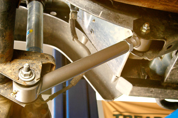
Illus. 60: Here is the right side lower control/link arm installed. Of note, the later TJ models have eliminated the use of an eccentric bolt/adjuster. Shown is a 2004 Rubicon with a non-adjustable, round washer at the caster (forward) bolt. (The brackets still show the caster adjustment marks.) A service kit, consisting of eccentric head bolts, is available from Jeep/Mopar and the aftermarket. This enables adjusting caster on a stock suspension system. In this case, however, the new FTS link arm lengths are fully adjustable, providing a means for adjusting caster angle.
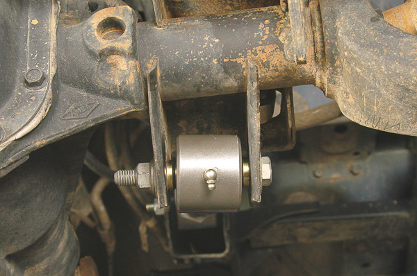
Illus. 61: Lower front joint is a swivel type. Grease fittings on the link arm heads provide a means for periodically lubing the joint. Attention to service details like this reflects quality. Many lift kits do not use a swivel joint nor do they provide grease fittings. This FTS suspension system has been engineered for long service. Compare features when considering a suspension package.
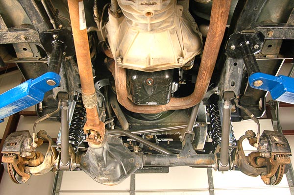
Illus. 62: Here is the installed front suspension system. Rear-to-front view illustrates the high-end components on this “short arm” package. The link arms attach at OE points, providing good wheel travel, off-road articulation and on-highway handling. Beyond 4” lifts, FTS offers a long-arm kit. This owner wanted 33” diameter tires and more ground clearance without the need for a long-arm package. 35” tires would require a long-arm approach for proper caster angle over the range of axle travel (“arc of radius”).

Illus. 63: This view shows the driveline still in place. I was able to install the entire front suspension system without removing the driveline. Keep the axle housing from rotating to protect the driveline from U-joint damage. On this lift package, the front driveline does not require modification. This driveline has a CV type rear joint and does not operate at a steep angle, even with the 4” lift. Driveline length measures within specification.
Caution—Always check drivelines for U-joint angles and shaft length. The spline coupler must operate within a safe range of travel. Too short, the driveline can uncouple. Too long, the driveline can bottom its spline coupler and damage the transfer case, U-joints, yokes or axle.
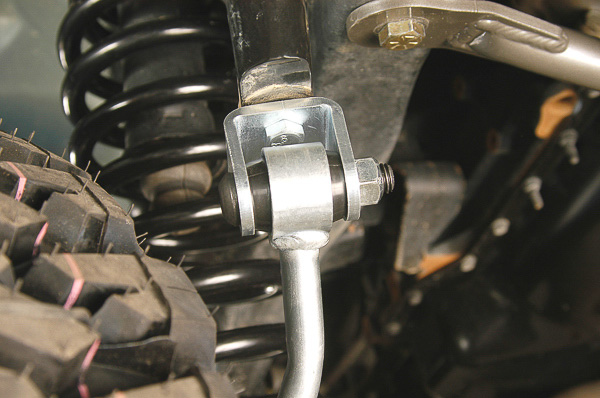
Illus. 64: Stabilizer links are upgraded to disconnect types. This hefty replacement item offers a means for disconnecting the stabilizer bar from the axle when driving off-pavement. Disconnects are popular for providing additional wheel travel and articulation. Links must be re-attached when the vehicle returns to highway use—otherwise, the handling, body roll and safety will be adversely impacted.
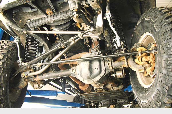
Illus. 65: This view shows both disconnect links installed. New 285/75R16 Goodyear Wrangler MTR tires on stock 16” x 8” Rubicon Edition wheels will provide the lift and tire size desired by this owner. The stock Rubicon offers one-inch more chassis height than other TJs to accommodate 31” diameter tires. 33” tire size requires an additional 3” lift on the Rubicon. This FTS package provides a 3” lift for Rubicon models and a full 4” lift over stock height on non-Rubicon TJ chassis. This works for 33″ diameter tires.
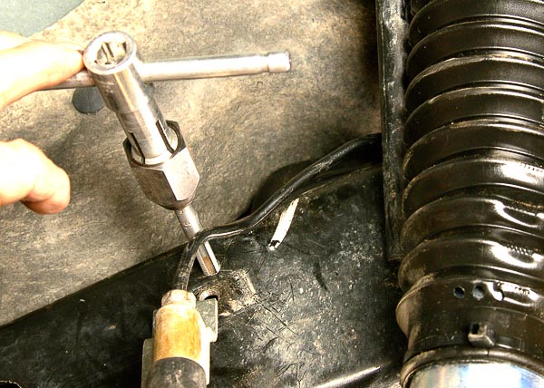
Illus. 66: At right side of vehicle, simply tapping an existing frame hole provides the right attachment point for the brake line drop bracket. I bend the pipe carefully and make certain that the tube routes safely at the top frame rail and around the shock tower. Brake pipe location is critical. Avoid rough edges, kinks, tight bends and stretched pipe or hose.

Illus. 67: This drop of the brake hose/pipe joining point enables use of the stock brake hose in this application. The hose will be checked for clearance with the axle at full drop, full height and steering from lock-to-lock. Some lifts require longer brake hoses, usually solved with the use of braided steel replacement hoses. Be sure hose does not kink, chafe or stretch too far. Make adjustments or relocation brackets if necessary.

Illus. 68: At the left side, the relocation bracket attaches to the OE frame thread hole. I carefully bend the pipe, making certain the pipe does not rub or chafe against the spring tower. Check tubing from the topside. Confirm that routing is safe and consistent with the OE approach.
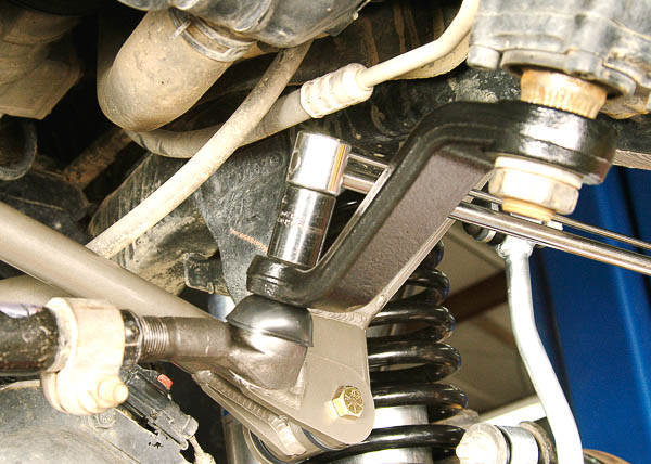
Illus. 69: Install the tie-rod end into the new pitman arm. If fitted properly, the tapered ball stud should seat and allow the nut to tighten without rotating the stud. On rare occasions, you may need to snug the stud into the seat. Use a large ChannelLock® pliers to squeeze the tie-rod and its ball stud into the tapered seat. Hold the tie-rod snugly while tightening the ball stud nut. Once the nut seats, you can apply the required torque and install a new cotter pin.
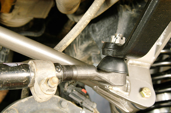
Illus. 70: Tighten nut to required torque specification. If a cotter pin hole does not align at the torque specification, tighten the castellated nut just the amount necessary to align the next cotter pin notches in the nut. Never back off a nut to align the cotter pin holes. The joint is designed for a required torque setting plus the necessary tightening to align the cotter pin hole.
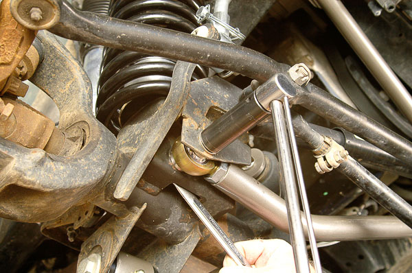
Illus. 71: The track bar has a Heim joint end at the axle. This joint fits the bracket with special bushings and hardware. I adjust the track bar to center the axle housing laterally with the rear axle. By keeping the axle assembly on stands and the frame on the hoist pads, alignment is not difficult. If alignment has been lost during your work, string lines from common rear axle check points, moving forward in cross (diagonally) and also straight fore-and-aft, can help reestablish the front axle alignment. The rear axle is still on the OE location points at this stage.
Note—If you are simply replacing OE control arms, they are of fixed length and require no adjustments. By contrast, the FTS system allows for considerable adjustment. Making the chassis and axles square is part of working with an adjustable suspension. Front axle caster can be somewhat determined by the front axle and driveline pinion angle. As necessary, the final adjustments can be made on a four-wheel alignment rack.
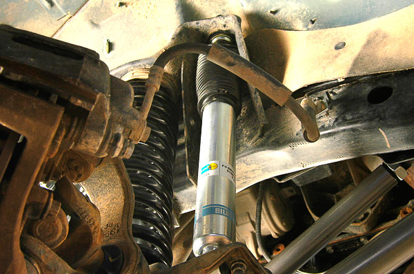
Illus. 72: With the axle at full drop and also weighted on the stands, move the wheels and tires lock-to-lock. Check for brake hose bind, stretch and risk of chafing. Always be certain that the brake hoses have enough clearance for maximum suspension travel. This is the left front wheel and brake assembly.
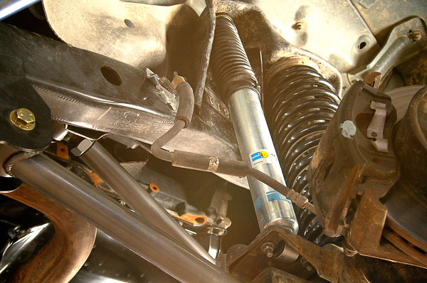
Illus. 73: Right side brake and wheel assembly requires a check. The hose has plenty of room in all axle and wheel positions. Being the OE hose, this is a secure, safe installation. The drop brackets have provided the amount of clearance needed. At no point was this brake system opened, so there is no need for brake bleeding.
See ‘Part 2’ and ‘Part 3’ for the completion of the FTS ‘Ultimate’ Jeep TJ Wrangler Suspension Lift System Installation!
When working on your Jeep TJ or LJ Unlimited Wrangler, refer to the factory (OE) Jeep® Service Manual for the vehicle model year. Torque specifications, frame specifications, the wheel alignment specifications, driveline torque specifications and suspension details—including torque settings and actual frame measurements—are available in the Jeep® official workshop manuals. I consider these manuals a “must” for any 4×4 shop or Jeep owner who is serious about performing professional level work. See your Mopar™ or Jeep® dealer for access to these manuals, available in paper-bound and CD format!
— Moses Ludel
Copyright 2010 © Moses Ludel…Enjoy this comprehensive, color-illustrated article and photography by Moses Ludel. The article is available solely at the 4WD Mechanix Magazine website and can be viewed here as often as you like. If you wish to share the article with friends or professional colleagues, please refer them to 4WD Mechanix Magazine website: www.4WDmechanix.com. As copyrighted material, this article and the photography cannot be copied or distributed in any other form.—Moses Ludel
