Overview: Jeep ‘PCM’ and Multi-Point Fuel Injection Systems
AMC electronic fuel injection for Jeep engines dates to 1987. From 1987-90, the 4.0L XJ Cherokee benefited from multi-point fuel injection. This reliable Renix system could easily have been adapted to the 4.2L six, a move that would likely have earned praise from YJ Wrangler owners. However, Jeep Corporation would finish out the 4.2L and 5.9L AMC V-8 eras with carburetion.
In 1991, the strategic shift to Chrysler’s proven multi-point (MPI), sequential fuel injection launched the XJ Cherokee and the YJ Wrangler to new levels of performance. The engine fuel and spark management computer (ECU) became the Powertrain Control Module (PCM) with broader responsibilities and more sensor input. Automatic transmission and chassis functions, including optional ABS, gained electronic controls and feedback sensors that make the 4.0L era YJ Wrangler (1991-up) and TJ models more versatile and responsive to modern emissions and performance demands.
Introduced on the 1991 2.5L four and the 4.0L six-cylinder Cherokee and Wrangler engines, Chrysler’s MPI boosted horsepower while delivering maximum fuel efficiency and a clean tailpipe. Noticeably, the fours delivered more power and an improved torque curve. Despite the loss of the long-stroke 258/4.2L engine, the new 4.0L MPI six in YJs refined and dramatically improved the multi-purpose highway driving and high altitude, backcountry trail-running experience for Jeep 4WD owners.
These MPI engine designs, well able to meet emission requirements and fuel economy needs, carry forth into the TJ Wrangler era. YJ 1991-95 engines and the TJ Wrangler powerplants are similar. Small differences on the TJ models include the switch to a filter/pressure regulator at the fuel tank with a single fuel supply line to the engine fuel rail. Also, the 1997-up MAP sensor mounts at the throttle body area of the intake manifold, eliminating the familiar MAP location on the firewall.
The XJ and TJ’s triple 32-Way and later TJ triple 35-Way PCM units replace the 60-Way PCM and mount conveniently at the firewall above the battery. All XJ, ZJ, WJ and TJ Jeep models comply with OBD-II standards for emissions, repairs, diagnostics, PCM updates and maintenance.
2000-up 4.0L MPI engines are distributorless, while the 2.5L MPI engine maintains its distributor through 2002 models, the last offering of the 2.5L AMC-design four. The 2.5L four dutifully served Jeep light utility 4x4s and SUV XJ Cherokees for two decades. MPI 4.0L inline sixes remain the highly popular engine option for TJ Wranglers, included as standard equipment on Unlimited and Rubicon models. Beginning in 2003, the 2.4L DOHC inline four replaces the 2.5L four as the highly reliable and efficient MPI/SFI base engine.
For reference sake and distinctions, I break the Jeep MPI fuel-and-spark management systems into distributor type and distributorless type. 2.5L YJ and TJ models through 2002 rely upon the distributor type ignition system. 4.0L engines through 1999 have ignition distributors. From 2000-up, the 4.0L engine is distributorless and uses a camshaft position sensor (CMP) with oil pump drive in place of the distributor. (1991-99 Jeep 4.0L MPI engines have the camshaft position sensor built into the distributor assembly.) Ignition coils at the spark plugs eliminate the need for spark plug wires on distributorless engines.

The camshaft position sensor (CMP) replaces the ignition distributor on 2000-up 4.0L engines. The oil pump drive and camshaft position sensor are a unit. The CMP on 4.0L MPI distributorless engines works with the crankshaft position sensor (CPS) to help the PCM separate and adjust spark timing and fuel injector events. The camshaft rotates at half the speed of the crankshaft, in sync with the ignition firing cycles. A worn timing chain can affect the CMP signal and conflict with the CPS data.
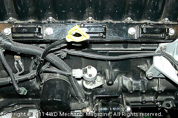
Coil gangs mounted in paired cylinder fashion attach directly to the spark plugs. Although not as convenient for spark plug service, the distributorless ignition fires far more accurately and fully in sync with millisecond signals from the PCM (powertrain control module). This advanced fuel-and-spark management brings the 4.0L and 2.4L engines to peak performance and the cleanest possible tailpipe readings.
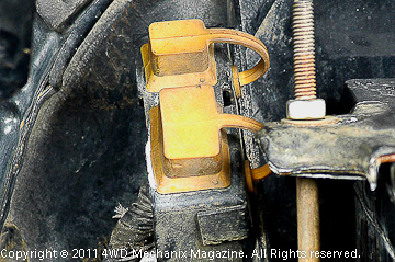
Diagnostics for the EFI/MPI systems follow industry protocols during the YJ and TJ eras. YJs, including the carbureted models, were of the DRB-II® tool era. OBD-II era TJs benefit from the DRB-III® tool. These tools point out specific problems based upon stored codes and actual interrogation of the engine and powertrain functions. Diagnostic connector plugs shown here are access points for troubleshooting early YJs with 6- and 15-Way diagnostics.
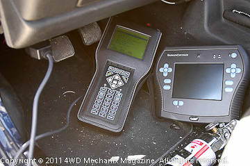
The 16-Way (pin) Data Link Connector on TJs rests just below the dashboard to the left of the steering column (left-hand drive models). This is common OB-II era diagnostics retrieval. Shown here is the DRB-III® tool in action (at left) and DaimlerChrysler’s StarSCAN® scanner tool designed to meet ‘Next Generation’ model needs and 2008 Federal/C.A.R.B. diagnostics and vehicle chassis wiring requirements.
Before moving into actual diagnostics and troubleshooting of Jeep MPI/SFI engines, an orientation to the fuel and spark management system is valuable. There is no better example of the system’s dynamics than to review the installation of a Mopar Performance MPI/EFI Conversion package. (See article in this series.)
This kit, derived from the similar 2.5L and 4.0L Chrysler MPI platforms introduced in 1991, consists largely of off-the-shelf components for the 1994-95 YJ Wrangler 4.0L engine with later TJ features included. This is essentially the equipment that launched the TJ Wrangler in 1997. With the exception of the distributorless ignition, introduced on 2000 4.0L engines, the Mopar Performance EFI Conversion Kit uses components commonly found on 1991-up MPI 2.5L and 4.0L engines.
MPI Devices and Troubleshooting
On Chrysler and DaimlerChrysler MPI/SFI systems, components are not difficult to identify. Armed with a stored DTC or your scan tool diagnostics, you can troubleshoot the suspected circuits or components. The aim of this section is to familiarize owners and troubleshooters with the devices and areas involved with common MPI fault codes. Testing and repairing these faults can quickly put a Wrangler back in service.
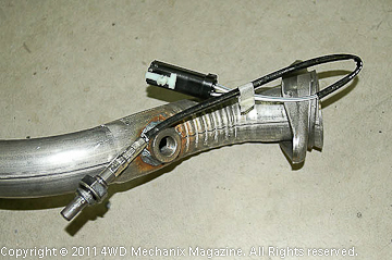
While the PCM operates in open loop and closed loop modes, the most significant advantage in closed loop mode is that the oxygen sensors provide input. The heated, two-wire O2 (oxygen) sensor provides the data for monitoring and adjusting air-fuel ratios. Optimal A/F ratio for gasoline clean burn (stoichiometric) is 14.7:1.
Oxygen sensor failure or faulting will send a DTC and force the PCM to run in open loop with a preset A/F or “limp home” mode. Proper oxygen sensor performance is vital.
Engine performance is considered in various “modes.” These modes are 1) open loop start-up, 2) open loop warm-up, 3) idle after warm-up in closed loop, 4) cruise mode in closed loop, 5) acceleration in open loop, 6) deceleration in open loop, 7) wide open throttle in open loop. There is also key-ON engine not running, which is open loop and, of course, the key-OFF mode. Each of these modes involves specific MPI, ignition and related devices. We can troubleshoot within the framework of the modes.
Engine Not Running: Key-ON and Key-OFF Modes
When the key turns to the ON position, several devices come into play before the engine cranks over. The PCM activates the Idle Air Control, setting it for start-up. A MAP sensor signal tells the PCM what the air/fuel needs will be. Additional advice comes from the coolant temp and manifold air temp sensors. An auto shutdown (ASD) relay turns on for a three-second interval while the fuel pump powers up. The ASD also starts the oxygen sensor heat up process.
The fuel pump will only run for three seconds with the key ON unless the engine is running or the starter motor cranks. If you question why the fuel pump stops running with the key ON, consider how long the key has been ON without cranking the engine. More than three seconds, and the pump stops. Key ON, engine not running is a busy mode!
Key OFF shuts down the PCM. This cuts off the injectors, the ignition coil(s), and any active relays for fuel-and-spark management, including the fuel pump and ASD devices. This shuts down the heat leads to the oxygen sensors. The PCM masterminds the powertrain functions and each mode of operation. Sensors provide necessary data for each mode of engine operation.
Start-up Mode and Trouble Spots
Start-up involves a number of signals to the PCM. Of immediate concern is the battery state of charge (voltage), the temperature of the engine’s coolant, getting crankshaft and camshaft position readings, and processing the TPS, MAP and MAT data. The PCM watches for crankshaft movement, activating the fuel pump relay for only three seconds if there is no cranking.
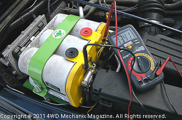
Battery voltage is an important signal. The system looks for a minimum of 12.4 volts. (This is just over a 50% state of charge.) Be aware that running a battery low with an MPI/PCM system will not provide a strong enough signal to the PCM. Here, this winch-equipped Rubicon TJ has a dual battery upgrade and a battery isolator to assure that one battery is always at a sufficient charge level for engine starting.
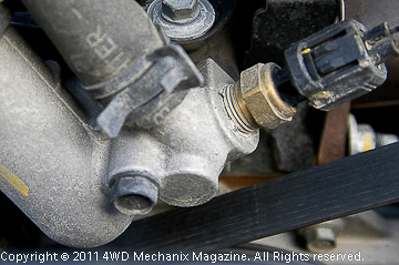
The coolant temperature sensor (CTS) is a common EFI device. Coolant is the quickest way to determine engine running temperature. The sensor mounts at the thermostat housing, the warmest source point to read temperature. This is where coolant exits after circulating through the engine. The PCM system will not work efficiently below 195-degrees F on a warmed up engine.
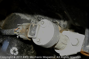
On 1991-99 MPI engines with a distributor (2.5L MPI fours through 2002), the camshaft position sensor (CPS) mounts within the distributor housing. On 2000-up 4.0L distributorless engines (as shown), the CPS is also the oil pump drive. The CPS device must be timed much like setting a distributor into place. The signal indicates precise camshaft movement. All MPI engines require a CPS signal.
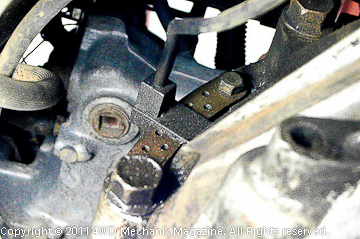
The crankshaft position sensor (CKP) is at the back of the engine above the flywheel or drive plate. This has been the location for the sensor as far back as the TBI 2.5L engines (shown here). A flywheel or drive plate trigger tooth pattern provides the signal for the sensor. The crankshaft position sensor (CKP in newer Jeep engines) is a vital PCM signal, sending a precise top-dead-center piston position reference.
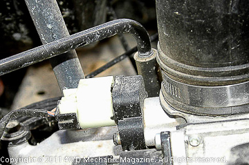
The throttle position sensor (TPS) is essentially a potentiometer that indicates the voltage setting for various throttle positions. Voltage increases over the opening range of the throttle valve. Since input to the TPS is 5.0 volts, the output reading should not read at or above 4.5 volts with the throttle wide open. Idle voltage at the throttle stop should be over 0.350 volts and under 0.900 volts. The need for an accurate digital voltmeter that reads 1/1000ths of a volt is obvious. (See the 2.5L TBI article for more details.)
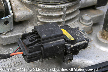
MAP sensor output voltage is 4 to 5 volts, which drops to 1.5 to 2.1 volts when the engine warms and the transmission is in neutral at an unloaded idle condition. This is a crucial signal for the PCM. (See the TBI article for more details.)
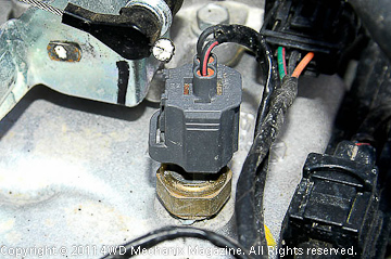
MAT sensor is at the intake manifold. Sending an actual manifold temperature signal to the PCM, this device is part of several operation modes. Mounted to the right of the throttle body on this TJ OBD-II engine, the MAT is easy to spot and change. If a DTC calls for replacing a MAT, torque the new MAT sensor to 20 ft-lbs. Do not over-tighten.
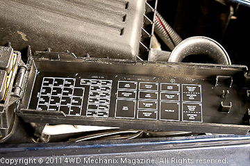
The fuel pump relay and ASD relay are each in the Power Distribution Center. This relay/fuse box unit is easy to access. Near the battery and labeled in detail, the PDC offers ready service of fuses and relays. Here, the map of relay locations quickly turns up the ASD and fuel pump relays.
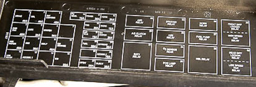
The relays lay in the positions indicated on the fuse/relay map. Find the relay to be tested. You can remove the relay and check across its poles with an ohmmeter and jumper leads. The voltmeter function can test power to the relay sockets. A Power Distribution Center makes access easier.
MPI Operation: A Warming Engine
During the warm-up cycle, the PCM stays in open loop mode. The PCM looks for each of the signals described in the cold-start and starting mode. There are two additional devices that enter the fuel-and-spark management equation: 1) whether or not the Park/neutral position is engaged on automatic transmission models and 2) whether an air conditioner equipped model has the A/C either selected or set into ON mode. These signals tell the PCM that the warming engine is under additional load—either in gear or with the A/C on. The PCM adjusts the idle through the Idle Air Control (IAC).
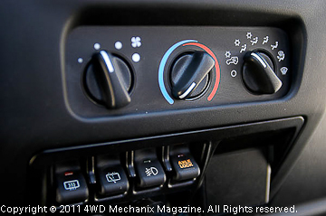
The power steering pressure switch on four-cylinder engines is on the power steering hose. This switch indicates a load on the engine when steering pressure increases at an idle. Placing an automatic transmission into gear will increase load at idle, and so will turning on the air conditioner (shown here). During warm-up and warm running conditions, the PCM compensates for these loads at an idle, increasing speed as needed.
Idle Mode: Switching to Closed Loop
As the engine reaches warmed stage, the PCM adds the oxygen sensors to its data resources. The injectors continue to fire by way of the PCM, which provides the ground for each injector to fire in its sequence. Injectors have positive (+) current at all times through the ASD relay when the engine is on. The PCM fires each injector by supplying the on-and-off ground circuit after reading and processing the relevant sensor data.
Following warm-up, the power steering pressure switch on 2.5L engines also comes into play. This switch will increase the idle speed slightly to prevent the engine from stumbling under heavier steering loads at idle. The switch will activate far more readily with oversized tires and while the Wrangler is rock crawling. TBI and MPI 2.5L engines require the power steering pressure switch signal to maintain a steady idle.
Now in closed loop, the PCM adjusts injector pulse width (flow), spark timing and the engine idle. The O2S (oxygen) sensors help maintain optimal air-fuel ratios under cruise and idle driving conditions. In meeting stoichiometric or 14.7:1 air/fuel ratio for gasoline, the fuel burns as completely as possible, especially with the dual firing, coil-on-plug (distributorless) systems. The PCM adjusts idle speed at the IAC. Air conditioning clutch cycling is through the PCM by way of the clutch relay.
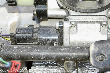
The idle air control (IAC) maintains the idle speed. The PCM adjusts the IAC to hold a steady idle. Four-cylinder engines benefit from a power steering pressure switch as well. The IAC “motor” mounts alongside the throttle body. This is an electrical device controlled by the PCM. Mounting screws torque to 60 in-lbs. The IAC has been a reliable, industry-wide mainstay device for MPI engines since the 1980s.
Highway Cruise Mode
Warmed and still in closed-loop mode, the PCM operates the cruise mode functions. I equate cruise to lighter loads, higher manifold vacuum and reasonable highway speeds. The upshift light on manual transmission models helps train drivers in how to maintain a cruise load level, avoiding unnecessary lugging or over-revving. Cruise loads are optimal for fuel efficiency and engine longevity.
At cruise mode, all of the warm idle functions are operative, and the PCM functions in the same way as other closed loop, warm engine modes. Interestingly, the PCM controls ignition timing by switching the ground path on and off to the coils. At this higher manifold vacuum driving mode, the engine delivers peak efficiency and fuel economy. Here, spark timing can advance, and fuel mixtures stay at 14.7:1. By contrast, heavier throttle uses more fuel, and hard acceleration requires fuel enrichment and a switch to less efficient open loop functions.
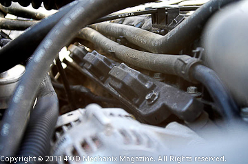
Whether distributor type or distributorless, the 4.0L MPI ignition depends upon the PCM for spark advance and retard. This function takes place by the PCM switching the ground path on-and-off to the ignition coil(s). On engines with coil-on-plug coil packs (shown), the coils fire cylinders at TDC of the firing and exhaust strokes. To do so, each coil fires cylinders paired as 1-6, 2-5 and 3-4 in the normal 1-5-3-6-2-4 firing sequence.
Open Loop Acceleration and Deceleration
Ever wonder why MPI engines with modern emissions packages still suffer poor fuel efficiency when driven hard? Sudden increases in the throttle opening, like a passing situation on a two-way traffic, two-lane road at the rush hour, tell the PCM to abandon closed loop. In open loop mode, the fuel injector pulse width widens to accommodate the need for acceleration. The PCM disregards the oxygen sensor signals and shifts to the acceleration air/fuel ratio programming values.
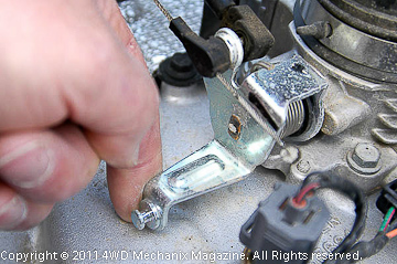
Air/fuel ratios normally adjusted by oxygen sensor signals will not work under hard acceleration (shown). In order to move a vehicle’s mass at an accelerated rate, the engine must run richer. While this impacts emissions, the downstream catalytic converter(s) and spark timing adjustments can balance out the occasional enrichment mode. The PCM delivers a pre-set, richer injector pulse width that remains consistent with open loop tailpipe emissions requirements.
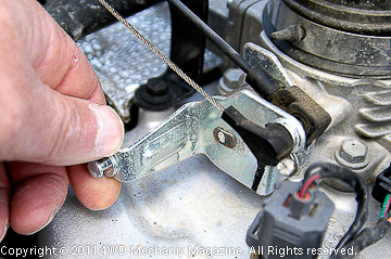
Hard deceleration is also an open loop mode. The cruise mode sensors plus the vehicle speed sensor play a role here. Oxygen sensors have no role, as the system must not attempt to maintain stoichiometric (14.7:1 A/F) with a fully closed throttle! If the throttle position is fully closed as shown here, the PCM will cut off all of the injector flow. If deceleration is gradual, the PCM will adjust injector pulse width (flow), spark timing and the IAC to stabilize the slowdown to idle. All of this is dependent upon the driver’s throttle demands.
Wide Open Throttle, Open Loop and the PCM
On BBD feedback carburetion systems and early TBI/EFI systems, the wide open throttle (WOT) switch is either on or off. On the MPI engines, the signals for wide open throttle come from the TPS and other sensor devices that serve during cruise and acceleration modes. PCM open loop adjustments of the injector pulse width/flow will meet the wide open throttle demand. The PCM continues to control spark timing by switching the on-and-off grounding to the coil(s).
The PCM routes the alternator field winding, fuel injectors, coil(s), some relays and some sensors through the “power ground” circuits. Whether responding to wide open throttle or other injector and ignition timing demands, the PCM uses these power ground circuits to complete the ground loop at constantly “hot” (+) devices. Ignition “dwell” and alternator charge rate are PCM functions.
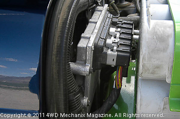
The PCM has a large role, with nearly 30 input signals from a variety of sensors, powertrain switches and sometimes the 16-Way Data Link Connector. There are nearly as many PCM outputs, several of bus type to cover a variety of functions on a single circuit. The PCM operates power ground circuits, monitors the cruise control and interfaces with brake, clutch and transmission signals. Better yet, with OBD-II, the busy PCM is also programmable and able to download updates as well as upload data and information! Shown is a late 4.0L TJ Wrangler’s PCM with three 35-Way connectors.
Composed with HTML Editor
