The YJ or TJ Wrangler clutch unit is a perishable item. At some mileage interval, preferably after years of quality service, you will need to address the removal and replacement of the clutch. When rebuilding the transmission, you have ready access to the clutch unit as well, so this is a very good time to routinely replace the clutch assembly, release bearing (hydraulic slave/release on 1987-92 YJs) and perhaps the crankshaft pilot bearing.
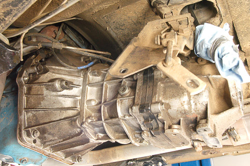
R & R 1: Here is the AX-5 ready for removal. If you are about to service the transmission or clutch, begin by carefully removing the transfer case, following steps in your workshop manual.
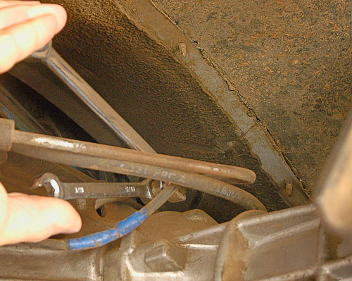
R & R 2: First clean then loosen the clutch fluid line. In this position, I am using two flare nut wrenches to prevent rounding corners on the fittings. Make sure that you identify metric versus U.S. wrench sizes before attempting to loosen hardware.
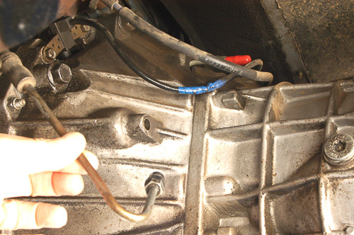
R & R 3: Drain brake-type fluid from the tube. Keep the fittings clean and free of debris. Like a braking system, the fluid must not become contaminated with debris or moisture. Cap off the ends securely to prevent fluid contamination. I recommend taking the time to flush old fluid from the system when servicing the hydraulic clutch system.
Note—Purge the hydraulic system using clean brake fluid. A brake vacuum pump bleeder serves well here.
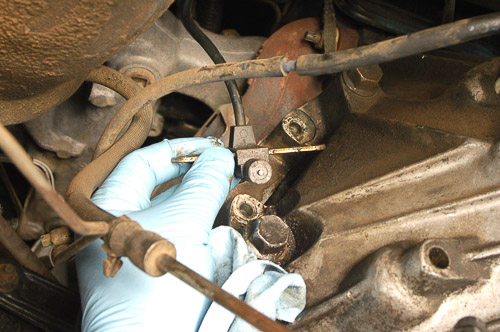
R & R 4: The crankshaft position sensor is an important part of the electronic fuel and spark management system. This sensitive device must be loosened and set aside carefully during transmission or clutch service. 1987-up four-cylinder models and 1991-up 4.0L models use a crankshaft position sensor. If the crankshaft position sensor mounts in this location, use care when removing it.
Note—Late overhead camshaft 2.4L ‘Power Tech’ fours use a block/crankshaft position sensor. All 2.4L and later distributor-less 4.0L engines also use a camshaft position sensor.
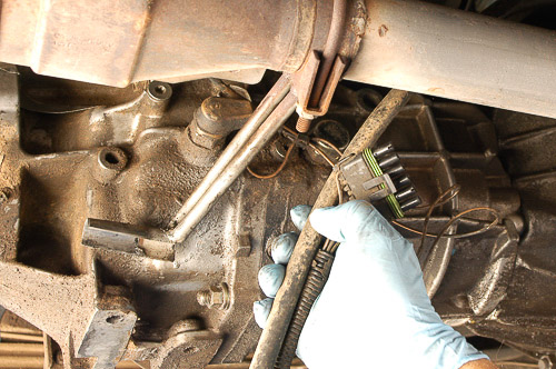
R & R 5: Look carefully around the transmission and clutch housing. If any wires attach or stand in the way of transmission removal, detach them and set the harness safely aside. When in doubt about the wire routing or clips, you can take notes and mark the harness with masking or duct tape. Make notations on the tape if necessary.
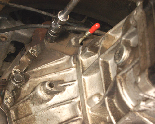
R & R 6: I loosen the most awkward to reach clutch housing bolts first. The transmission and clutch housing must come out as a unit. These top bolts can be loosened with an extension, swivel and socket. I access the bolts from above the transmission housing. Apply force squarely to keep the socket in place. Don’t bust your knuckles!
Suggestion—If necessary, lower the transmission unit slightly, not so much that the engine or exhaust system becomes bound and no more than 3-inches. Do not allow the engine to crush parts against the firewall! Keep your transmission jack beneath the transmission to support the unit. Support the engine with a block of wood atop a support stand beneath the oil pan.
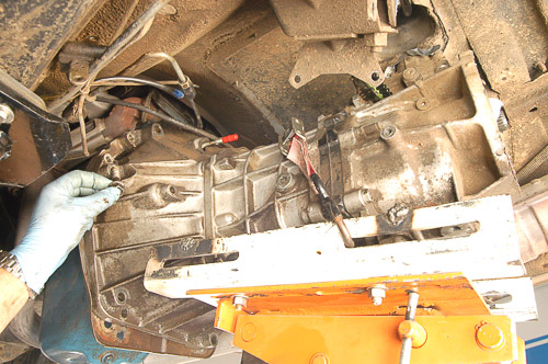
R & R 7: Before removing the last bolts at the clutch housing centerline, make sure the transmission is carefully secured to the transmission jack. Keep the engine supported if necessary. Do not allow the engine to hang or bind the transmission during removal. The four-cylinder engine (shown) balances nicely without much support. Note the iron intermediate plate that indicates this is an AX-5 transmission.
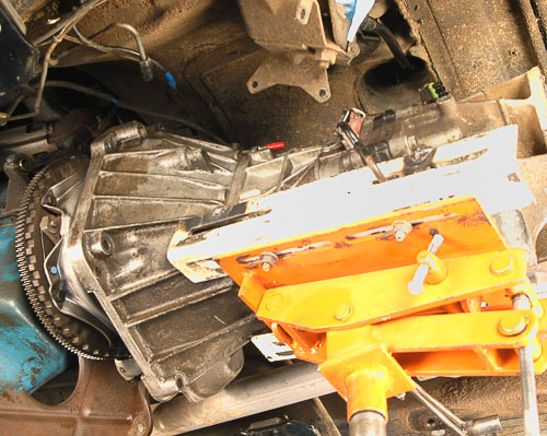
R & R 8: The transmission must come directly back from the engine. If the engine/transmission is on a slope, set your transmission jack to maintain that angle as you slide the transmission rearward. You do not want to bind the transmission input shaft in the clutch hub or pilot bearing. Keep the clutch housing face parallel to the engine block and flywheel face. Adjust the engine/transmission assembly as necessary.
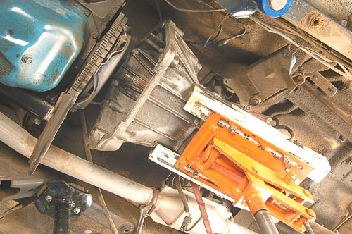
R & R 9: Here, the input shaft is free of the clutch unit. This transmission can now be lowered. Be careful, and make certain that the transmission input is free of the clutch fingers as you lower the unit. Note that the lower dust cover hangs loose and free of the transmission. Six-cylinder engines use a spacer plate or “shim” that often covers the full clutch housing edge. It, too, hangs behind the flywheel.
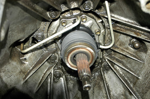
R & R 10: This is the internal slave cylinder/release bearing assembly. Busy and inaccessible from outside the clutch housing, if this slave leaks, the clutch disc could easily become saturated with brake fluid and fail. In the field, this would be a nightmare to access. If you stick with this system, always replace the release bearing hydraulic slave assembly when installing a new clutch! This will be cheap insurance, for sure.
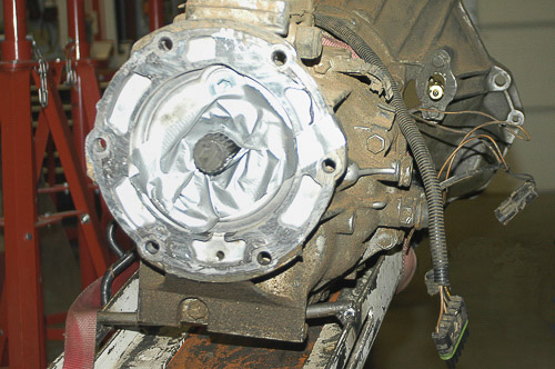
R & R 11: This AX-5 unit has its wires in place and safe. You can see the bleeder valve at the right side of the clutch housing. If you disconnect the lines, air enters the system and requires bleeding upon reassembly. You can bleed the system here. The output shaft of the AX-5 and Peugeot BA 10/5 is 21-spline. AX-15 and NV3550 units have a 23-spline output. If you upgrade to an AX-15, include an NP231 transfer case with a 23-spline input and the correct input gear. (I refer to the “Spline Count Concerns When Upgrading to the AX-15, NV3550, NV4500 and Other Transmissions” in my article on identifying Jeep Wrangler transmission and clutch types.)
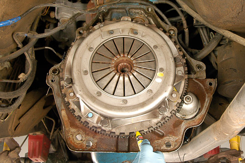
R & R 12: You now have access to the clutch disc. Before removing the unit, mark the flywheel and clutch cover position for reassembly (if you intend to reuse the clutch cover). Always mark the relationship of parts that must remain in balance, including driveline pieces, yokes, clutch units, splined hubs and wheel hub-to-brake rotor assemblies.
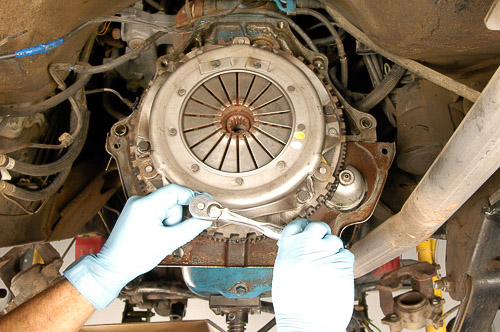
R & R 13: Loosen the clutch cover bolts evenly, a few threads at a time. You can distort and damage a clutch cover by tightening—or loosening—one side too far. This also applies to reassembly of the clutch. By tightening uniformly and in cross, a few turns at a time, you can keep the clutch disc from moving off center.
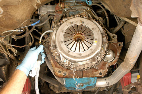
R & R 14: Well, here’s another use for my Ammco 1450 Brake Washer! I purchased this machine to minimize the hazard of brake dust—and clutch disc dust. Older clutch units and even some replacement discs contain asbestos. The use of a brake parts washer helps protect our lungs. Note that once the clutch cover allows for slight space between the pressure plate, disc and flywheel face, I flood the entire clutch assembly with brake washing solution. (This is a water-soluble cleaner that should not damage rubber parts.)
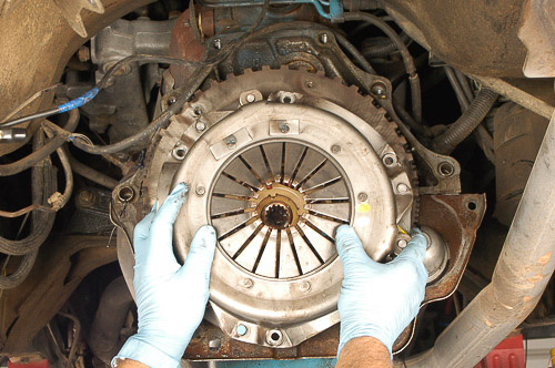
R & R 15: Remove the washed down clutch assembly. Wet and flooded to flush out clutch dust, this clutch is safe to handle. I place the unit in the brake washer basin for further cleaning before storage.
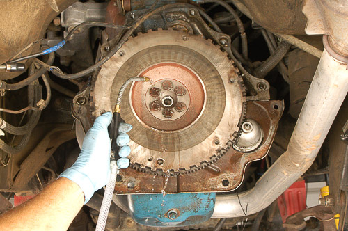
R & R 16: Now, the flywheel surface is accessible. I use the brake washer nozzle and solution to wash down the flywheel face. There is a cleaning brush that also flows with cleaning solution, and I carefully clean the flywheel. This is a 1987 YJ Wrangler, and there is good reason to suspect the presence of asbestos clutch lining. The flywheel shows resurfacing during a previous clutch replacement, and the composition of the clutch disc is unknown.
Safety Note—Newer model YJ and all TJ Wranglers were equipped from the factory with asbestos-free clutch discs. (By 1994, the OE clutch lining does not contain asbestos.) Non-Mopar replacement clutch units, however, may contain asbestos. The safest approach is to assume that any brake and clutch lining may contain asbestos. Treat these parts accordingly.
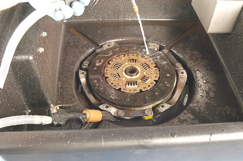
R & R 17: Here, I am soaking and cleaning the old clutch disc and cover. Before I set these parts aside, they will be free of any friable particles or dust. The clutch is nearly new, and it could be reused—not on this YJ, however, as an inline six will soon replace the 2.5L four. I am grateful to have the Ammco 1450 Brake Washer, a sensible investment for working on older YJ Wranglers and other Jeep 4×4 models!
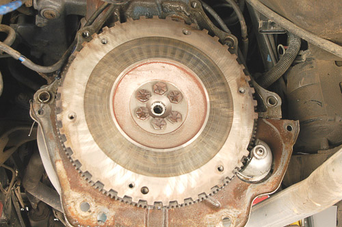
R & R 18: Clean and clearly visible, the flywheel appears flat and in reasonably good condition. This flywheel has been resurfaced, and not that long ago. Look for bluing, cracks, glazing and any symptoms of warp. This flywheel could be hand scuffed with 180-grit emery paper (0.001”-0.003” maximum material removal) and deliver good service. You could use a disc sander and lighter grit emery, but do not remove more than the glaze and 0.003” maximum material. A disc sander applied evenly would keep the surface flat. Note that the pilot bearing is easy to inspect at this point as well. Check for a concentric bore and wear.
Caution—If in doubt, you can check the flywheel surface for warp with a dial indicator or true straight-edge. Make sure that the flywheel runs true. Be aware that later flywheel surfaces have a special “contour” from the factory; resurfacing is not recommended, as it will remove this contour. With the clutch disc snugly on the transmission splines, you can check disc face runout with a dial indicator. The new clutch disc must not run out more than 0.020” measured at 1/4th inch from the outside of the face. Frankly, even that runout figure is higher than I would like to see.
Copyright 2010 © Moses Ludel…Enjoy this comprehensive, color-illustrated article and photography by Moses Ludel. The article is available solely at the 4WD Mechanix Magazine website and can be viewed here as often as you like. If you wish to share the article with friends or professional colleagues, please refer them to 4WD Mechanix Magazine website:https://www.4wdmechanix.com.As copyrighted material, this article and the photography cannot be copied or distributed in any other form.—Moses Ludel
