Enjoy the many detailed, traditional ‘Q&A’ exchanges in these article columns…’Q & A’ has now moved to open, interactive forum discussions. Visit the forums, you’ll want to join—for free!
Have technical questions about your Jeep 4×4, popular 4WD truck, SUV, ATV, UTV or dirt motorcycle—or welding and metal fabrication? The 4WD Mechanix Magazine ‘Tech and Travel’ Forums now feature enthusiastic discussions and input from members and our staff, including comments from Moses Ludel…
For an HD video playlist, featuring the latest Q&A vlogs with Moses Ludel, click here for the “4WD Vlog and ‘Live Tech’ Q&A Channel”.
Want to discuss your technical and outdoor interests with like-minded enthusiasts? Check out the 4WD Mechanix ‘Tech and Travel’ Forums! Click here for a guest visit to the forums!
The amount of stress that most Jeep and other trail 4WD rigs experience makes welding a regular chore. Frame cracks, twisted bumpers, broken brackets, repairs on broken and damaged equipment and fabricating accessory mounts are just some of the Jeep 4×4 welding demands. Then there are the trailside fixes…
Miles from nowhere, you want things to stay together! If you need advice on how to properly weld or fabricate Jeep components, here is the place. Whether you’re mixing metal types, repairing castings, welding, brazing or soldering, Moses Ludel can answer your questions!
Just writeout your question on the E-mail form and submit the E-mail directly to the desk of Moses Ludel! Moses will personally answer questions, as promptly as practical, in the order received…Meanwhile, look through the ‘4WD Tech’ and ‘Q & A’ sections for similar questions and answers.
Welding Axle Shafts for Strength?
From: Jay B.
Sent: Thursday, September 27, 2012 2:34 PM
To: 4WD Mechanix Magazine
Subject: RE: Axle shafts…
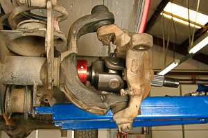
Hi…I am running a Dana 30 with 33 km2’s… looking at upgrading to a 44 up front eventually… but until then was wondering if stitch welding would increase the shafts strength? I do know that welding could warp the shaft and could poten
So picking up where I left off… potential to really mess up my housing.
My plan was to stitch welding the Axle in quarters (one line the length of the shaft on four opposing sides) down the length of the shaft and the about every six inches making a loop around the shaft in opposing direction eveytime.
I have searched all over for an answer to this question. You seem like the best source to help me out.
Thank you for your time,
Jay B.
Hi, Jay…Axle shafts are case hardened alloy, commonly treated by carburizing method. If the shaft draws too much heat from your proposed welding, this could reduce or eliminate hardening at the splines. Soft splines will pulverize without proper hardening.
Metallurgically, if you weld the shaft in its case hardened state, the weld areas become “normalized” (unhardened or even annealed) and have varying degrees of irregular hardness and stress in the heat affect zone (HAZ) surrounding the weld beads. The stock axle shaft design has a core that is yielding and ductile, allowing for slight flex and twist, and a hardened surface—at least at the splined sections.
Attempting the strengthening method you describe, I would begin with “normalizing” the shaft in a heat treating furnace. Once normalized, the shaft could be welded, using care not to warp it. The weld filler material needs to be heat treatable with the same alloy characteristics as the shaft’s base material. (Weld Mold Company offers niche filler material that is chemically like with the axle shaft base metal in an annealed state. The filler would be heat treatable with the same results as the base metal.) Welded and straight, the shaft could then be re-heat treated to the hardness and depth of the original case hardening.
This all said, the weakness of the axle shaft is around the spline area, and all of this work would not embellish the strength of the spline sections. In fact, by stiffening the axle shaft driving sections, you would be placing far more stress at the splined sections. The shaft would lack its original ability to flex and twist (within the normal range of the alloy’s ductility). There would be a high likelihood of axle spline failure or shearing/breakage of the axle shaft near the splined section.
Splines are the weak area by design. The undercut metal and space between splines is a void, lacking the strength of the solid sections of axle material. It is for this reason that replacement/upgrade axle shafts have more splines; this lessens the void space and provides far better load distribution.
My recommendation is to “survive” with the stock axle shafts until you can afford the changeover to the 44 up front—or consider what I did with the XJ Cherokee: keep the 30, switch to 30-spline axles of quality (Superior in my case), and install lower ratio gears (higher numerically) with an ARB Air Locker. (See articles at the magazine site.) On both the XJ with 4.10 gear swap and my son-in-law’s YJ Wrangler with 4.56 gears, the 33″ tires have been no issue.
The Dana 30 operates only in 4WD modes. In high range 4WD, it receives 50% of the torque applied to the rear axle in high range 2WD. Low range, there is equal torque applied to each end. With the torque split, a 30 isn’t that bad after all. A “Super 30” with 30-spline axle shafts, improved alloy and stronger steering U-joints can do the job in most instances. The bigger concern is actually axle tube diameter and stamina, which does not get better with a stock Rubicon 44, only with a retrofit heavier (truck or aftermarket) axle. A cross-housing truss can help here if you like fabricating and welding!
Trust this helps, Jay…thanks for the interesting question. I’m here if you have more.
Moses
Reinforcing a Vintage CJ-6 Frame for a Tire Carrier?
From: Raymond
Sent: Monday, October 01, 2012 6:30 PM
To: 4WD Mechanix Magazine
Subject: to box or not to box
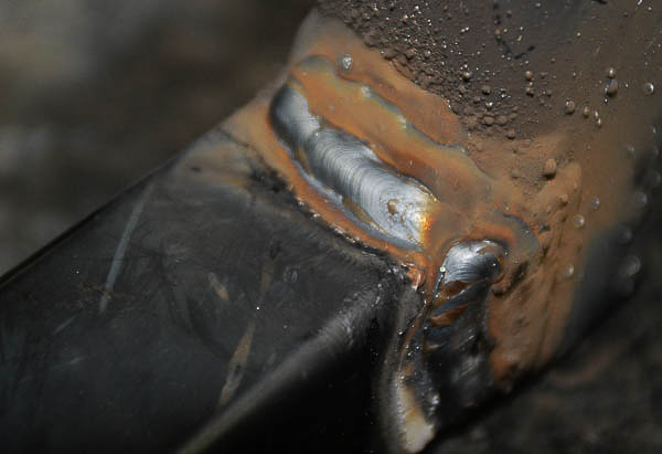
Sorry, this gets wordy: CJ-6, I removed the drawbar/trailer hitch assembly and the two drawbar to frame supports for the fuel tank underneath like later models. the owner wants a BIG rear bumper with a bumper mounted spare tire swing (33″ tires). those rear frame rails need help. if i box the inside of the frame from the rear bumper forward to the first cross member (just aft of the pumpkin) do i create a stress/fold point somewhere in the not reinforced frame where it passes over the rear axle ?? or do i plate the outside of the frame rails from the bumper forward over the rear axle to a point where the frame gets straight and is reinforced some ??
Raymond
Hi, Raymond…Although you do not mention the year of the frame design, your concerns are well founded for any CJ-6. All of the CJ-era frames flex—considerably, by design. You’re right in noting that reinforcing one section of a frame places more stress elsewhere. There are precautions that you can take.
A traditional way to add frame members or “stretch” a frame by adding a section is with the use of diamond or “fish” plates. This is a joining process, not an attachment like the bumper you propose. Here is a recent exchange I had with a friend and hardcore trail runner. He has an ‘80s CJ-8 with the factory “boxed” frame, and the frame developed a crack. Read my exchange with Mark B. in the next Q&A below.
Some points in my comments to Mark B. apply. An advantage with the rear section of a CJ-6 frame is that the rear springs trail from anchor points at the front end of each spring. I’m still not in favor of stiffening the frame much, and my angle-cut plates would have gap areas to allow more flex yet. This would be a sensible way to “box” the C-channel CJ-6 frame. Following the lower diagram, I would cut the plate ends at even more of a diagonal angle than represented in that drawing. This would allow flex while not stiffening the frame in a way that leads to fractures or shearing angles—like straight vertical lines would do. The diagonal offsets allow some flex yet raise the strength in the frame section. Stitch welding permits more flex and helps prevent loading at one point.
Keep in mind that the Jeep frame must flex. Consider the frame part of the suspension. Later CJs (’76-’86) the YJ Wrangler, TJ Wrangler and JK Wrangler models built successively more stiffness into the Jeep frame. The CJ-6 is easily as flexible as the CJ-7 frame, since the CJ-7s have a boxed frame. Many CJ-6 models use traditional, riveted cross members.
All of this said, I would consider making a bolt-on setup for the rear bumper/tire mount. Make long side plates to take forward alongside the frame, or if easier, emulate the forward running, diagonal braces used on the drawbar hitch. If you’re suspect that the brace bolts will put too much stress on the frame at one point, consider boxing the frame with shorter plates (6”-12” length) on the inner side. Diagonally cut the ends on these plates as noted, and make stitch beads around 3” in length.
Where the bolts go through the plate and frame, insert steel sleeves between the rail and plate. Use sleeves with decent wall thickness and an I.D. the size of the bolt shanks. This will keep the frame rail and plate from crushing when you tighten the through bolts. Sleeves will also distribute load more evenly, over more surface area.
Bolting the assembly to the frame provides less loading and does not require as much modification or welding at the frame. Make sure the forward running bumper mounting plates are wide. Stagger the bolt holes.
The OEM draw bar hitch mount points might support a bumper and 33” tire if you reinforce the frame attachment points and use the forward braces. The Jeep drawbar hitch should have at least a 150 pound tongue weight capacity, there may be specs floating around from an old install kit that provide tongue rating.
As a footnote, the rear Warn bumper on our XJ Cherokee supports a 33” (hefty) spare and has forward arms that are quite short. Warn made this a “bolt-on kit”, using factory bumper mount points on this thick sheet metal unibody. Bolt-on bumper kits may provide ideas. Winch mounts and front plow mounts provide additional solutions.
Weigh my comments and opinions. We can continue this dialogue.
Regards,
Moses
Repairing a Jeep CJ-8 Frame Tear
From: Mark B.
Sent: Thursday, August 16, 2012 2:51 PM
To: 4WD Mechanix Magazine
Subject: Frame fix
tnx for the helpful responses. The frame crack is not a big issue to repair—will grind clean, weld up and maybe a small plate on top of frame rail. i like how it migrated to the hole and stopped—for now.
tnx again
mark
Hi, Mark…The hole is a typical stop point…Grind a “U” or “V” at the crack to permit a full penetration weld. I use a die-grinder with a burr-grinding carbide tip for this. The tool, available in several diameters, has a round end that makes a uniform, controllable cut.
If you’re using 1/8” electrodes and stick at 120-130 amps (set to your preference), you can probably do a single pass, forming a decent crown and full penetration through the frame…Additional plate is okay if you stitch weld it in place. Do not run full length beads on a rectangular or square patch piece.
I’m into stick process at the welding tutorial section and will be demonstrating shortly.
Moses
From: Mark B.
Sent: Monday, August 20, 2012 1:59 PM
i discovered the frame is pulling apart– right at the right rear spring forward leaf hanger. Cracked about 5″ fore and aft of the hanger and the the frame halves are separating. uh oh… its always something. So now this new crack and the other one = lots of time w/ the die grinder and rotary files. argh!
mb
Mark, from what you describe, the frame has cracked where additional loads occur. The area you describe is in some ways similar to the loads applied at the break point on ’72-’75 AMC/Jeep CJ frames. Here, the front frame section breaks where the leaf spring anchors drive force into the frame rails. For the ’72-’75 AMC/CJ, the issue gets compounded by the boxed front frame section abruptly becoming a C-channel rail behind these front spring anchors. The front section has been stiffened; the C-channel has to flex over a shorter distance; the frame breaks at the junction of boxed and C-channel frame.
The combination of your huge unsprung weight mass with the Ford E-truck full-floating rear axle, the oversized and weighty tires, plus the shock loads of the trail, contribute to a high stress point at the frame. Also, when you “stiffen” one area of the frame, the normal torsional twisting of the frame (over the length of the frame) is compromised. (Example: One adds plate to stiffen the mid-frame sections or widens the track width with a wider, rigid beam axle and wide tires; twisting forces along the frame end abruptly at the stiff, unyielding frame points, resulting in frame cracks.) Your CJ-8 frame cannot flex or transfer stress away from the spring anchor points on the frame rails. The frame cracks or breaks right there.
Despite the boxed factory frame approach with the ’76-up CJs (surely a move forward!), these frames are actually quite flexible. I’ve held one end of a bare (brand new) CJ-7 frame with someone holding the opposite end. You can twist the frame nearly a foot end-to-end—by hand! When you patch your frame, keep this intended torsional flex in mind.
Also, when you repair a vertical frame crack as you describe, you never weld the section together with a butt weld (unless the butt weld is made strictly for alignment while you set up a patch repair). The only “factory” repairs described for truck frames (like old I-H notes to dealers on how a farmer or rancher could stretch or add a frame section) use a fish or diamond plate patch. Diamond (four-sided) or fish-plate steel plates were typically welded inside and outside the C-channel frame rail. The diamond centered at the cut or break line. In your case, the CJ-8 frame is boxed and not C-channel, so you would need to improvise.
The idea is to provide angled lines for the welds, which spread the stress over this larger area of plate. This way, the welds will not be vertical/straight at the frame break. Note that with four-sided diamond or fish plate patches, there are no rectangular or 90-degree countering forces in the patch.
Another approach is to make a channel steel section to lay over the frame at the break point. You could diamond or fish-plate one side of the boxed frame at the break point. At the opposing side, you would center the channel section over the break point with channel overlapping outwardly in both directions. Weld with stitch (non-continuous) beads along the straight section (at the top and bottom). That channel section, from the side view, would have parallel, diagonally cut ends.
You’d have to notch for the frame/spring hanger and so forth, and the diagonal ends should be more slanted. Note the goal: no vertical welds or stiff, vertical stress points.
By contrast, if you simply grind out the current cracks and weld them as a vertical butt repair, the force against that weld will continue to be overbearing. Also, you’re messing with the metallurgy of the frame-versus-welding rod material. This leads to incompatible ductility (yield and elongation) at the weld. The result can be an even greater load along the weld edges. Then there is the added issue of tensile strength and the heat affected zone (HAZ) alongside the welds. Gradual, air cooling helps with this kind of repair—to avoid granular or “crystallized” metal, do not quench with water or cold air.
For each of these reasons, the fish or diamond plate repair, or a brace section made of large channel material, offers the best fix…Realistically, the CJ-8 frame was not designed for your large axles, oversized tires, stiff leaf spring stacks, wide track width, hefty unsprung weight mass, ultra crawl ratios and continual pounding over rock piles with a trailer in tow! You’ve actually done fairly well, considering…
Moses
Ready for Welding Class!
—–Original Message—–
From: Dan R.
Sent: Sunday, April 15, 2012 7:37 PM
To: 4WD Mechanix Magazine
Subject: Welding class enrollment
Hello,
Would you be able to tell me how I go about signing up for the online welding classes. I can’t seem to find the link.
Thanks, Dan
Hi, Dan…Thanks for your interest in the welding sessions! The course sessions online begin May 1st. There is no need to “enroll” officially. Expect the traditional course approach: gas welding, brazing and cutting, followed by stick welding, then MIG process and TIG. I will add extra projects to illustrate the processes as the course proceeds…
Glad to have your participation. Please feel free to ask questions at any time…I’ll add HD video sessions steadily until the full course, covering all of these processes, is part of the magazine website.
Regards,
Moses Ludel
Welding or Repairing a Jeep Frame
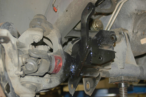
From: John M.
Sent: Friday, August 26, 2011 12:34 PM
To: 4WD Mechanix Magazine
Subject: Dumb question…
Hello,
Sorry to have to ‘ask’ this and I suspect I know the answer from contents of your website but- I keep hearing rumors saying that welding on a jeep frame weakens the frame. Now this makes no sense to me since 1.) I’ve looked at your website and I see you folks welding on frames and 2.) I see the guys over on Powerblock TV welding on frames all the time!!
So what is the real skinny here! I hear that the frames are heat treated and that welding on them is bad, etc, etc, yet the OEM frame has welds and I see people welding on frames.
Is a buzzbox stick any better than Mig when welding?
Figured I’d ask and have the real scoop!
Thanks much!
John M.
From: 4WD Q & A
To: “‘John M.'”
Date: Friday, August 26, 2011, 2:59 PM
Hi, John…This is not a “dumb question” at all. There are times when metal can be grossly affected by welding. If a piece is heat treated or of uncertain composition, welding can weaken, damage or diminish the integrity of parts.
You bring up a good point about frames. All frame weldors should qualify why and when it is okay to weld on a given frame member. The material used in most conventional frames is intended for production jig or robot welding, and these metals can often tolerate the heat involved in the welding process if cooling takes place properly. Then there are the structural concerns like whether welding a piece here or there can actually upset the design intent and function of the frame. (We can discuss “reinforcing” frames some time and why making a frame rigid in one place can actually cause breakage elsewhere.)
A rule of thumb for field welding an automotive or light truck frame is to “air cool” the assembly without interfering with that process. Do not quench, water cool or rapid cool the assembly; otherwise embrittlement or irregular granular structures in the metal will result. Hard spots can be avoided, or at least reduced dramatically, by the air cooling of parts.
Another overlooked issue is the welding filler material. If the frame is of special alloy or even a mix of alloyed metals, there may be special requirements for filler material. If you notice, I am very particular about metallurgy and never take a “seat of the pants” or anecdotal approach in this regard. I enjoy research and a serious approach to metals fabrication. This includes concerns about whether an alloyed metal, like popular 4130, is in an annealed (non-hardened) or heat treated state before welding. Note that in my 8620 cluster gear repair, I first normalize (similar to annealing) the case hardened metal, then weld it with a 100% compatible material for 8620. I will case harden after welding and machining, and both the base gear material and the weld filler must behave like 8620 in a carburizing heat treating process.
So, the matter-of-fact, let’s go weld on a frame approach is not the whole picture. Especially with modern hydro-forming and other processes, automotive frames may require a special metallurgical approach when welding. Unitized bodies (like the XJ Cherokee) are even more of an issue, as they are largely made of heavier sheet metal stampings that have their own chemistry and needs. Here, the approach would be ICAR-approved methods found in the auto body industry…
I like to be academic and scientific. Others may take another approach. Expect metallurgical and process insights when I weld, and if you have any questions whatsoever, please feel free to ask, John!
Moses
John back…
From: John M.
Sent: Friday, August 26, 2011 4:05 PM
To: 4WD Q & A
Subject: RE: Dumb question…
Moses,
Thank you for your informative email and quick response! I really appreciate you taking the time to explain the science behind the concept.
Basically, I was asking as I noticed my Jeep CJ 5 frame has a crack on the inner boxed portion underneath the cross plate that hold the radiator. I don’t believe this crack is due to stress on the frame per se as the outter potion of the frame is fine and w/o defomation. However it does appear that at one point either someone took a BFH to the inside portion of the frame (for whatever reason) or else someone did something they shouldn’t have and ended up concaving it the section of frame. Of course there is an OEM recessed squared section of frame not far from the deepest part of dent and *SURPRISE* it seems that the corner set up a stress location.
Obviously I’ll stop drill the crack but wanted to be sure that I could weld it up w/o hurting the frame. From what you’ve told me, it seems as though doing such would be a safe.
By the way: I read your section on the gear repair. All I can say is “WOW”, you really know your stuff and do some very nice work.
Cheers,
John
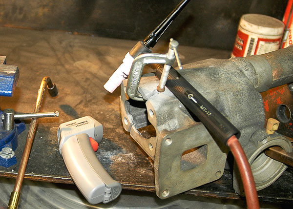
From: 4WD Q & A
Subject: RE: Questions.
To: “‘John M.'”
Date: Tuesday, August 30, 2011, 12:41 PM
Questions are welcome, John. This exchange will be of benefit to others through the welding Q&A.
You can cover just the hole and damage, that’s okay. I was thinking more cosmetically and how you could make this all look “factory” while creating a permanent repair.
From your photos, I visualize flat plate covering just the open section of frame rail, between the welded members. The idea would be a piece that looks at first glance like part of the original layout. This is not a large area, so plate size would be moderate. The goal is to make the welds look like the factory bracing welds.
Draw me an illustration or photograph a cardboard mockup (in place) to confirm that we’re on the same page with the repair…You should still have the winch option when done; you’d simply need to drill the correct size hole through your fresh plate and the frame wall.
If the plate size is larger than anticipated (provide approximate measurement), there is the option of a few button-hole welds placed diagonally down the plate. This is done by drilling holes of ½” diameter through the fresh plate, then button-hole or “plug” welding the plate to the frame rail at these holes. You would then weld around the outside of the plate as described earlier…If the Jeep were here, we’d have a nice how-to welding project!
Moses
John’s photos…
From: John M.
To: 4WD Q & A
Subject: Questions.
Moses,
Here are some pictures. You’ll have to forgive the lack of quality. From what I can see, the hole in the frame is re-enforced with a spacer. However with the ‘dent’ in the inner frame it has seemed to have misaligned the holes. Again, I don’t know if this was due to a winch or not but whatever did it was a doozy.
John
From: 4WD Q & A
Subject: RE: Questions.
To: “‘John M.'”
Date: Tuesday, August 30, 2011, 6:31 AM
Hi, John…I read each of your latest replies…Glad you have enjoyed both of my books!
I see this is a ’76-’86 CJ model. You can do the frame repair with wire welding (MIG with shield gas preferred over flux core). Stick (SMAW) is okay if that’s the equipment on hand, preferably 7018 rod for this repair. Clean metal as much as practical with a wire wheel; use a surface grinder lightly if needed…Since there are additional steel members near the damaged area, a plate could be fitted to look “factory”. I would weld the plate at the top, ends and bottom with continuous beads.
The frame being boxed type with cross members, continuous beads should not create a problem in this short section. (Stitch welding would be smart if frame twist were likely here, which it is not. If the frame was C-channel design and cracked, I would use a fish plate or a diamond shaped patch and the stitch welding method.) Stitch welding, beads run with space between them, is an option on your project; however, continuous beads will seal out rust-forming moisture, which is an issue in some environments.
Quality E70S-6 welding wire, 0.035” diameter would be fine, offering plenty of tensile and reasonable ductility. The patch plate can be 1/8th inch thick mild steel if you reinforce this plate with button hole or plug welds. Use thicker 3/16″ to 1/4″ plate if you only weld around the perimeter of the plate and do not add buttonhole or plug welds.
Since you’re doing all this, consider a shackle reverse kit. The kit can improve handling. See how the current shackle reverse kits fit up. You may find it practical to incorporate a frame repair and shackle reverse.
Be certain to prime and paint the repaired section properly. Rust likes to form at welds and freshly welded, mild steel plate.
I’m pleased to answer any further questions or clarify concepts. Keep me posted…
Moses
John back…
From: John M.
Sent: Tuesday, August 30, 2011 2:47 PM
To: 4WD Q & A
Subject: RE: Questions.
Moses,
Thank you for all your input. I really do appreciate all of it and I’ll see what I can come up with. Right now, I’m just leaning towards fixing the crack and not plating it. I’m not going for pretty as much as functional and lasting.
So with that, I’ll stop drill the crack and will email you pictures of the project as it happens.
Cheers!
John
Good, John, I understand. Drilling a hole at each end of a crack can often be practical before welding.
A better approach here would be use of a round-head burr grinding tool to scarf out the weld crack to its root. That way, your weld root pass will burn through the backside and fully fill to the depth of the crack and frame metal. I like to burr down to a thin section of metal that will burn out as you make your root bead. Done this way, you could fully fill the trough and frame thickness, leaving no voids, then surface grind to mask the repair.
I use an air-driven die grinding tool with a ¼-inch diameter burr tool for the scarf operation. This makes an opening wide enough to burn into the metal and fully mate with the frame rail material. The weld(s) must have complete penetration, be free of voids and burn into adjacent base metal. If you make more than one pass, successive passes must burn into base welds as if you are welding pipe. No voids, occlusions or gaps will create a weld as strong as the original frame.
Moses
Want to Learn Welding?
I’ve been following 4WD Mechanix since the premier issue. You hint about teaching shop skills and welding. Can you teach me to MIG weld the bottom of my Jeep frame—without it looking like one big drip? This weekend I found I was better off using 6011 rod and the AC buzz box!—Craig T.
Yes, Craig, I plan to teach MIG and TIG. See the magazine’s articles and examples of cast iron TIG repair. (Non-ductile, gray cast iron is tricky!) I plan a monthly series that will include stick (SMAW), MIG (GMAW) and TIG (GTAW). We’ll include brazing and oxy-acetylene welding, too!
I have a humorous story to share about my first encounter with MIG, years before I taught these skills at the adult education level…I was adept at oxy-acetylene and stick (SMAW). I could do all-position stick and so forth, having schooled with the Operating Engineers Union at field repairs and working for years with structural automotive welding. My pal, Kirk Rogers, a budding millwright at Oakridge, Oregon, offered me the use of his home shop, quite a generous gesture! Fabricating motor mounts with a MIG, Kirk asked if I’d like to try all-position welds at the rear frame hitch. He was surprised when I could do nothing more than stick the wire! What a disaster…So I know how you feel about going from stick to MIG. Adding insult to injury, everyone boasts about how easy MIG welding can be. But it is a different “feel” than stick, and if you trained strictly on stick, MIG is a distinct transition…After mastering MIG and ultimately teaching the subject, I look back on that first MIG “event” with a smile. (I’m sure Kirk does, too!) Welding is a process, or I should say, several “processes.”
I plan to share all aspects of welding. We’ll take a textbook, professional approach. (No shooting from the hip or anecdotal nonsense. There’s plenty of that floating around.) Welding is serious stuff, and we’ll get your skills and confidence up to par. I honed my teaching skills with the tough students at Rite of Passage—many began my classes with their arms folded. Many completed the program capable of structural steel welding. Of the two star TIG students, one became an aircraft turbine weldor. Several students certified at advanced I-CAR auto body and frame repair, so we should be able to get your frame welding and repair skills to that level.—Moses
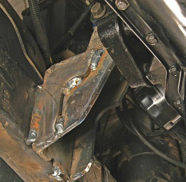
Which Battery-Powered Trail Welder?
Note from Moses: Below is a dialogue with Dave Logan that brings to light portable welder choices and concerns. This exchange prompted the “On-Board Welder Series,” which begins with Part 1, the Ready Welder segment at: Jeep Trail Welder Series: Portable ‘Ready Welder’.
From: Dave
Sent: Wednesday, August 11, 2010 2:52 PM
To: ‘Moses Ludel’
Subject: RE: Ready Welder
Hey, Moses!
I have a quick question. I recently purchased a used Ready Welder kit…without batteries. Any suggestions on what batteries would be appropriate for welding 3/16” or less steel on the trail? Ten minutes or so of actual welding time should be sufficient. I’ve been told that back up batteries from computer UPS systems are small, light, and sealed.
Moses, I rarely break anything and will probably carry the welding rig in my tow vehicle most of the time. When I do a remote multi-day run, I will find the space for it…probably in my M416 military trailer along with the camping gear.
Any help is appreciated!
Thanks,
Dave
From: Moses Ludel
Sent: Wednesday, August 11, 2010 6:11 PM
To: ‘Dave ‘
Subject: RE: Ready Welder
Hi, Dave!
I’m not familiar with the Ready Welder’s amperage demands. If high (I suspect), most would recommend a deep cycle battery if there is no alternator/charge input. Gel and mat batteries have become acceptable alternatives for some uses. The main idea is that a lead acid automotive battery does not do well with high amp, continuous drainage. Automotive batteries work safely when drain is minimal and recharge amperage is not extreme.
The danger is a hot, discharged battery or batteries that receive a high amperage charge input. If ignited from the slightest spark, this can cause a dangerous gas explosion. Avoid discharging a battery to its extreme then hitting it with high alternator output. Avoid sparks around the battery, too! A deeply discharged battery should be recharged slowly, without heat exposure.
Let’s look at the Ready Welder specifications for actual amperage draw and battery recommendations. This will determine the ampere-hour or CCA recommended. You want batteries that will not fail due to the drain down and recharge cycle. Likely, they will suggest a deep cycle or gel type. I would think deep cycle if you want a ‘standalone’ (non-charged) electrical source. These welders run typically on multi-batteries, series connected to produce 24V (two 12V batteries) or 36V (three 12V batteries).
Regards,
Moses
From: Moses Ludel
Sent: Thursday, August 12, 2010 10:54 AM
To: ‘Dave ‘
Subject: A footnote…
Dave…I looked at the Ready Welder and Hobart Trek 180…Each has its pluses. Ready Welder has a sophisticated spool…Well conceived for what it does. My only concern would be weight, specifically lugging heavy batteries around. Have you considered a Premier Welder with high output alternator? I’ve always used an onboard, alternator-driven welder, although the battery welding technique has been around for years.
Let me know how this works out and please send some photos of the setup! It sounds like a useful adjunct for severe backcountry travel…A quick story about a Rubicon trip and two guys with a CJ-5 steering gearbox bracket that broke loose from the frame: They had no welder and were steering the Jeep with a tree limb. When we came upon them, their progress was 250 yards in two hours! Fuel was near empty…Now that’s a place for your Ready Welder!
I assumed the use of deep cycle for the reasons Ready Welder cites. Apparently, the battery packs get used without recharging, which makes safety sense. It does mean that you need to carry a pair of extra batteries. In these group sizes, they weigh 15 or more pounds each. Sounds like AGM batteries, sealed, would be safest for your portable welding plans. Make sure you have adequate amperage per battery.
This is all very exciting. I want to hear your experience, how you hook this all up, where you carry the extra equipment, how well it works in the field and so forth! I have a passion for welding and taught the subject at the adult education level for five years…I’d like to play with the Ready Welder!
As a footnote, I use the Battery Tender on each of our vehicle and trailer batteries. This is the greatest boon to battery life. In the winter, each of our vehicles is continuously charging when parked, without the risk of overcharge, plate damage or problems. By keeping an automotive battery fully charged (not overcharging), you can extend its life 3-5 years. The killer is a discharged battery that starts the vehicle then encourages the alternator to slam high current into a low voltage battery. Deep cycle batteries are a totally different design: They discharge completely, without charge input, then take a full charge back up. That’s the reason the welder benefits from deep cycle batteries…If you have the time, I would use a Battery Tender to recharge the deep cycle batteries, without risk of overcharge or sulfating the batteries!
Are you planning to run flux-core with a spool gun? Or stick?
Best,
Moses
From: Dave
Sent: Thursday, August 12, 2010 9:20 AM
To: ‘Moses Ludel’
Subject: Ready Welder II
Hi, Moses,
I did not consider the Premier Power Welder because I already have a York air compressor system under the hood and space is limited. And, it costs $1,265.
The new Hobart Trek 180 is great, but costs $1,100 and that is more than I want to spend right now. [http://www.hobartwelders.com/products/battery-powered/trek180/] I paid $250 for my used Ready Welder II. A friend of mine had it and never used it.
Regarding battery types, the company’s FAQ section states: http://www.readywelder.com/faqs.php
As per your suggestion, I do have Battery Tenders for my motorcycle and such, a great product. Regarding the welding method, as you mention, I’ll use .035 flux core steel wire in the MIG spool gun.
Thanks again for your advice. I’ll update you once I get the batteries and use the welder in the field.
Regards,
Dave
Cracked Dana 60 Axle Housing Repair
From: Jake M.
Sent: Friday, October 01, 2010 12:51 PM
To: Moses Ludel
Subject: Dana 60 cracked housing
OK, Moses, I got one for you…I ordered some Rancho springs and they got here on Thursday. I got them on Thursday night and yesterday I took the Jeep out, flexed it up and got my shock mounts set at the proper height. All is going well so the only thing I had to do was finish welding my front drive shaft and weld the mounts for my anti-wrap bar. As I’m under my Jeep welding my driveshaft (since I found it to be the proper length after flexing the Jeep), I see some oil on the bottom of my just-installed front Dana 60 axle. It wasn’t my pinion seal or my diff cover…I saw what looked like a crack in the case below the ring and pinion. I pulled the diff cover and it looks like when the axle was under another vehicle it was jumped and the bottom of the front differential hit a big rock. So, now I have to figure out a way to weld the casting. I did research and I have welded for 20 years, just not much on cast steel.
My plan is to get some 55% nickel welding rod and weld the cracks on the inside of the diff and on the bottom. What sucks is I have to pull the front tires, brakes, hub, axle shafts and ring gear and Detroit locker to grind a notch where the cracks are and then fill them by welding.
If you have input into this I would appreciate it. I know you can weld cast by preheating it or cold. If I weld it cold it’s my understanding that I only weld about 1″ at a time so the cast doesn’t get too hot. Otherwise I can preheat it and weld it. After welding both are supposed to be “peened.”
Let me know if you have input.
Thanks,
Jake
From: Moses Ludel
To: Jake M.
Subject: Dana 60 casting crack
Date: Fri, 1 Oct 2010 13:31:39 -0700
Jake, I, too, have been welding a long time (45 years), and I taught welding at the adult ed level for years…We’re each skilled, and I have good news. In my research on cast iron, I stumbled across Weld Mold out of Brighton, MI. I’ve attached an article I did on a major cast iron repair. You will see and read some very interesting facts that accompany my TIG repair. If you have MIG and no TIG, Weld Mold may have 700 and 750 wire for MIG. Read the article and understand why you can use this material with radically reduced risk of cracking, which is the number one challenge with non-ductile iron. In the Dana 60, you have some margin, as this is a more ductile iron type and somewhat weld-able.
I am convinced that you can repair this housing to better than new by following these methods. Better yet, I have preheated to 500-degrees F and I have also run successive beads without preheat (once the welding has started). The warmed piece and continuous welding did not cause problems or cracking. I did wrap the axle casting in a welding blanket immediately after welding and between welding stints to allow very slow cooling. The repair illustrated took place over three days. I would not use any other rod than Weld Mold; it has the carbon content to produce graphite and allow more yield as the weld cools and shrinks.
Note: Axle housings are generally more ductile or “nodular iron” and sometimes can be welded successfully with “ni-rod.” I’d would want to know the metallurgy of a Dana 60 center housing before leaping into the use of nickel-iron rod. Let’s go from there, Jake!
Moses

A cast iron crack is not always easy to find. On this rare, vintage steering gear housing, a poor casting of gray iron produced this inherently weak area. Trace cracks to each end.
From: Jake M.
OK, I’ve read the entire article and learned a lot, thank you. My problem is I only have a 220V arc welder and a 110V MIG welder. I have access to a 220V mig welder. I’m going to look up the Weld Mold you suggested. Do you have tips for using the MIG? Can I do it with my 110V? The casting is only 1/8″ to 3/16″ thick at the most. I feel that with grinding the cracks to a “V” notch which I have been doing, it should be enough? Thanks again for you help. Also, do you feel that plating it with some 1/8″ mild steel would be wise. I sure do. I KNOW that the bottom of the differential housing is going to take a beating from rocks. (I know my style of driving way too well!) I have built my CJ Jeep to go where I want.
Thanks again,
Jake
From: Moses Ludel
Hi, Jake…You can weld the housing with stick and your 220V arc welder, although removal of slag is more work and must be done thoroughly. You’ve read my article and now know the “secret” of Weld Mold’s 700 and 750 cast iron rod. It has a high carbon content which helps form more graphite to help eliminate cracking as the welded area shrinks. Since the graphite content is higher, there is more “give” that may not be present in generalized “nickel-rod.” Tensile of Weld Mold 750 material is higher than a standard casting, and the rod is available in “stick” (SMAW) electrode. I only use Weld Mold’s niche welding rods. Look closely at the photos attached, and you will see that I welded mild steel plate to the iron axle housing very readily, using Weld Mold 750 filler rod material.
Check out the Weld Mold website:
Weld Mold 750 (choice number one; read description at Weld Mold): http://www.weldmold.com/index.php?option=com_content&view=article&id=98%3Aweld-mold-750&catid=7%3Acopper-and-nickel-alloy&Itemid=17
Weld Mold 700 (nice to have around; read description at Weld Mold): http://www.weldmold.com/index.php?option=com_content&view=article&id=95%3Aweld-mold-700&catid=7%3Acopper-and-nickel-alloy&Itemid=1
The other item to note is cool-down. After your last pass, you must immediately surround the housing in a welding blanket and allow it to cool slowly. I cooled an iron axle for nine or more hours between welding sessions. If you must interrupt your welding, plan on wrapping the hot housing in a welding blanket (high temp resistant type that will not burn or melt). Cooling too fast is disastrous. Air cooling is unacceptable with iron.
I have crack-free results because I do use Weld Mold 700 and 750 on iron. I also peen the weld/piece thoroughly between each weld pass. Rap uniformly and with a steady, firm hand, using a ball-peen hammer. Do not whack, but be firm, because the goal is to diffuse the graphite into the weld and make sure it mixes with the iron and other elements. Weld Mold suggests optional preheat to 500 degrees F with a torch before welding, with restoring that temp between passes. My experience is that you can preheat the weld area before your first pass, and if you’ll simply stay with the welding and keep the area at a steady heat during the repair welding, you can complete the job without need for additional torch heating. This saves a lot of acetylene and oxygen! Results seem the same. The key, again, is the yielding nature of 700 and 750 rod. From what you describe with the Dana housing, the generic ni-rod welds are shrinking too much as they cool, and that’s how the cracks form. 700 and 750 will not shrink to that degree.
If you want only one of the electrode types, I would pick Weld Mold 750 for your axle housing…High tensile and likely to weld without need for preheating after the first pass…You can join mild steel to the iron with this material. Read details at the link I provided…
Moses

Once the crack was thoroughly discovered, including die burr grinding to be sure of its fissure direction, a hole is drilled at the crack’s end to stop the spreading.
From: Jake M.
You just answered several questions without me asking them! I don’t have a “heat blanket,” I do however have welding blankets. Do those work sufficiently? If not, would it help to get some insulation and put that between the housing and welding blanket? I do have a non-contact laser type temperature device I could use to measure the temp of the housing before I heat it. Also, if I use the rod you suggest it sounds like I don’t have to wait to weld the entire crack? With the nickel rod they suggested welding at 1″ intervals at the most. With the 750 rod it sounds like I could run a continous pass without stopping. Is there a way to not have to wait 9 hours between welding sessions? That is a long time to wait! LOL
I’m going to pursue the Weld Mold 750 today. Out of pure curiousity, would it help to use a torch to keep the nickel rod warmer during cool down or would that do something really bad?
I can’t thank you enough for the help. The thought of having to exchange all of my compenents to another axle housing is really discouraging, expensive and time consuming.
Jake
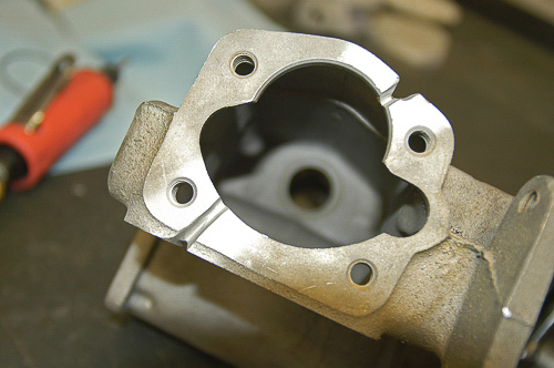
Here, I route out the cracks to their root in the casting, using a round-headed burr tool and air powered die-grinder. I leave just enough original material at the root to burn through with the first welding pass, assuring full penetration of the material.
From: Moses Ludel
Jake…A welding blanket is fine, as long as it does not melt or burn through from a nearby heat source. The idea is to contain the heat within the blanket and not let any cold air get to the weld or casting.
I use an infrared temp sensor like you describe…That’s a great tool and helps you stay aware of the temp in the weld zone. You’ll find it very interesting that the just-welded area cools rapidly to less than 300 degrees F. This is still warm enough to keep welding with 750 rod. I weld until the work is done and do not stop longer than the time necessary to peen rapidly with the hammer. You can see from my article how long each weld is, approximately the length you describe of one-inch…I would stitch and come back, so as to avoid intense heat and a long zone to peen. Peening is essential for diffusing the graphite. It just makes practical sense to keep the welds shorter…You’ll be able to peen the weld area thoroughly before the first section of each weld cools too much.
The nine hours of cool down were when I stopped for the day. That axle casting was a huge TIG project and took days to do, 2-3 hours each day with the welding hood on, plus the photography time. Stick will go much faster, you may be able to do the whole job in one session, but keep the weld area warm the entire time. As soon as you pull away from welding for a lengthy break time, cover the casting/housing in the welding blanket.
Nickel rod likes a warmer weld area, and since heat dissipates rapidly into a large casting, it tends to drop temp quickly in the weld area. I would use the blanket rather than any “creative approach” (avoid cooling the project gradually with a torch). A rosebud is an expensive use of gas and not really productive for slow cooling. With a big iron casting, the heat will just keep dissipating. Better to try and finish the job and wrap it safely in the welding blanket while hot.
I understand your concern about swapping housings. Done properly, this housing should work as well as or better than new. I have a great deal of confidence in Weld Mold’s very specific filler materials for the tool-and-die industry. The web links should clarify and help assure confidence about these products and how/where to use them…
Sounds like you can shape and weld a nice mild-steel “skid plate” beneath the repaired crack. If you “V” to the casting root, consider backing up the weld repair with your skid plate, burning into the mild steel from the inside of the housing. Then, with the steel plate tacked well to the weld root in the ‘V,’ you can make your successive beads to fill the ‘V’ at the former crack area. The edges of the shaped/formed mild steel plate can be stitch welded to the outside/bottom of the housing. This will look very “trick” and should help reinforce the weld area some.
As an important note, I use a carbide grinding tool/bit and die-grinder to make an appropriate “V” in the crack zone. With iron, always make sure you drill stop holes at each end of the crack, or the crack will return and spread beyond the original crack lines. Do not try to “stop” the cracks by welding. Drill the stop holes at the end of each crack and fill each drilled hole with quality weld as you perform your welding repair.
Moses
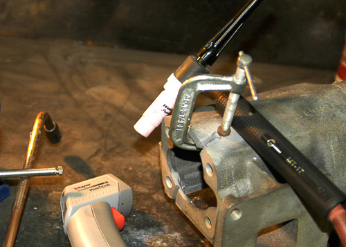
For additional strength, I back up the open section of casting with steel plate. This will be TIG welded thoroughly with the root passes. The Weld Mold 750 rod works well here. The plate is permaent and welded securely at the inside edges.
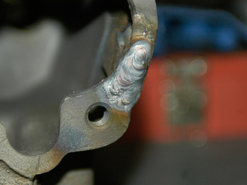
While Jake talks about stick electrodes, I take advantage of TIG welding and filler rod. TIG done properly has great penetration with virtually no risk of undercutting at edges. After practice, predictable iron repairs are possible, especially with materials like Weld Mold’s 750 and 700. This section received several passes with peening after each weld pass.
From: Jake M.
I did drill 1/8″ holes at the end of each crack before starting. I had learned that before in prior projects and learned that it’s even more important in cast iron. I’m proud to say that I successfully welded the cracks with the high nickel rod I had purchased. It wasn’t that I didn’t want to spend more money, it was more of a determination factor at work, and I did it. My arms are tired from peening the welds! It’s come out pretty darn good especially for welding upside down! I can lay one hell of a bead on flat, vertical…OK, upside down was always hardest. It didn’t start out too well; those welds cracked and I completely ground them away. I did V notch each weld and filled from the botttom up. I’m actually very excited that I seemed to have pulled it off! Now I just need Glen to plasma cut me a piece of flat mild steel to weld to the bottom of the cracked area. I don’t want to come down on a rock while out on a trail and find all my gear oil dripping out and have a broken housing again. It just makes good sense to me to put it on. I really can’t believe how thin the bottom of that portion of the casting is! I bet it’s not more than 1/8″ thick where it cracked. And it’s a big flat area just behing the bottom ridge that the differential cover bolts to. I looked inside the differential, and it got good penetration. I didn’t want to resort to having to pull the axle shafts, ring gear and Detroit Locker and weld on the inside, too.
I must say, with a Detroit in the rear 14-bolt axle and the tight turning radius of the front Dana 60, my Jeep turns SSOO great compared to the old welded rear 60 and front 44 that I had reduced the turning radius on (to save the axle U-joints from breaking when turned hard). The body doesn’t stay leaned to one side like it did before because of the welded rear diff. I haven’t even wheeled it yet and I love the upgrade!
Anyhow, hopefully all is well with the cracked diff now. I sure appreciate you input and I’m still going to try and get some of the Weld Mold rod on hand…Well, the repair should be finished. Here are pictures of the weld on the diff, with the plate being put on and then the finished product. I took it out today and wheeled it a bit in 4wd. So far so good, I’ve parked it and there hasn’t been a drop of oil or any cracks appearing around the patch. It was all done without heating up the cast prior to welding. I got 55% nickel rod from Napa (forget the brand) and had to weld very little bits at a time on the cracks and then on the patch I welded about 1″ at a time while rotating sides and letting it cool in between going back to the same place. I pray it keeps holding, I REALLY don’t want to have to go through that again! It was quite a learning curve but once I got it, it wasn’t too bad. This was my first experience welding cast.
Moses, thanks for the help and the advice!
Jake
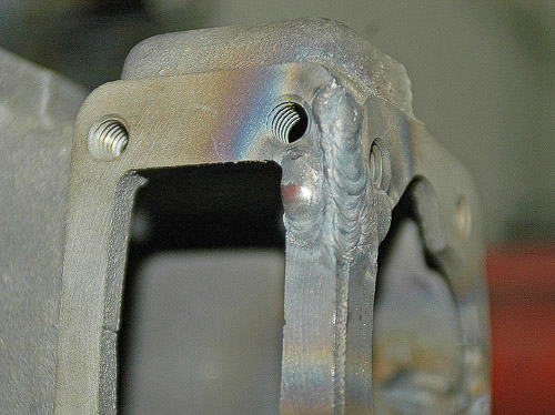
Area built up with weldment to produce a strong surface after machining. This will be a better casting than when new. I found the project challenging and gratifying, as there were no replacement castings available. TIG is controllable and produces these results!
From: Moses Ludel
Nice, Jake…I like the “finished product.” The steel plate is an additional leak seal and helps prevent impact damage at the welded area. The crack repair welds look ample, especially for the awkward welding position. Looks like a winner! If it’s leak free, you nailed it!
Moses


Finished vintage steering gear assembly is a “blueprint rebuild” with a repaired and improved cast iron housing. I milled and finished the casting (upper and middle photos) to receive the internal, close-tolerance components. It is gratifying to bring a rare or obsolete assembly back to “as new” or even better condition! After primer/sealer paint, there is no trace of a cast iron weld repair.
Note: For cosmetic touch-up work or minor porosity fixes on cast iron, I use high tensile, high temperature silver brazing rod, special flux and an oxy-acetylene torch. For repairing a load bearing piece like the vintage steering gear housing or Jake’s cracked Dana 60 axle housing, I opt for bona fide fusion welding, using cast iron specialty filler rod like the Weld Mold 750 and 700. TIG (GTAW) is my preference, MIG (GMAW) and stick (SMAW) would be my next choices—in that order. TIG requires exceptional cleanliness at all times during the repair work, making TIG my in-shop approach. Jake did well with his “field repair” method, with overhead access only, using stick technique. (See Jake’s photos below.)
Thanks, it definitely wasn’t easy to weld underneath the axle! I’m glad it is still holding and not leaking. I took the CJ Jeep out yesterday and wheeled it, put some torque on the front axle, etc., and it held. Again, I appreciate the help.
Jake
Good job, Jake! The mild steel skid should help, too…Weld Mold 750 has higher tensile strength than the typical nickel rod. Smart to get some 750 for future use and store it dry…
My guess is that this will all work out fine, because the nodular iron dilutes with the ni-rod during the welding, which creates additional strength. Also, the area of your axle housing that cracked is not a structural zone, and the nickel is somewhat ductile and yielding, more so than chromium. With the skid, you’ll be fine as long as the weld zone is non-porous and oil tight! And, yup, those housing castings are thin! They aren’t designed to support the weight of vehicles on rocks. Good lesson for others here. Send me some photos of the repair, I’d like to see your overhead stick job—good work, Jake!
Moses
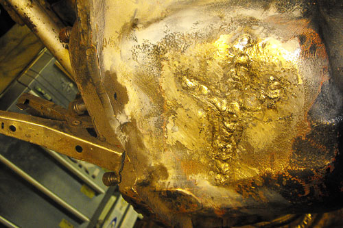
Jake chose to weld his cracked Dana 60 housing in-position (overhead), with all gears and shafts still within the housing! This is much like a trail repair—if you can get all of the oil out of the unit and weld area. With an on-board welder, Jake would be a popular guy on a rough trail in an emergency. (Jake’s three photos.)
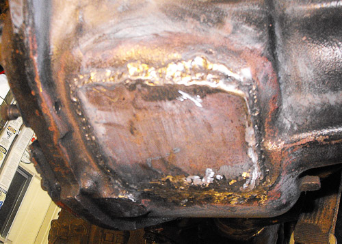
Jake’s Jeep is a rugged trail runner, mostly Sierra trails like the Rubicon and Blue Lake Area. He knows this axle housing will meet rocks regularly. To protect and reinforce the housing, he shaped and welded a steel plate to the bottomside of his weld repair.
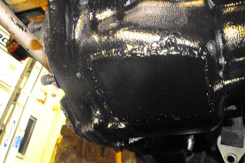
Partly for cosmetic reasons, partly for protection and added thickness, Jake welded a mild steel plate to the bottom. Fresh paint has this hard trail beast looking good again. The CJ boasts a Dana 60 axle at the front and a 14-bolt G.M. axle at the rear!
The photos look good, Jake…This will likely hold. If iron survives the weld process, it usually goes for the duration. 55% nickel is ductile enough to take severe trail pounding, which you will likely provide with this axle! From your description, the repair area is not a structural stress point or load area, unless you plant the Jeep axle on the rocks…Enjoy your success and keep me posted!
Best,
Moses
Jake Moves to the CJ’s Rear Axle Housing!
From: Jake M.
Sent: Friday, November 05, 2010 10:38 PM
To: Moses Ludel
Subject: Rear 14-bolt axle
Hi, Moses!
The one ton axles are holding up GREAT. I’ve been pushing them hard and doing minor adjustments to the steering, suspension, etc. So far it’s working great. I love how sharp the 60 turns, the four wheel disc brakes, how the updated suspension feels and so far the weld-patch on the 60 is holding up great. I’ve actually been trying to hit the bottom of it so I can make sure it’s going to hold. I’ve hit it pretty hard so far and not a single leak or new crack (knock on wood for me, please!). I unfortunately found that my rear 14 bolt was bent by a prior owner. I know it’s not from the kid I got them from. He had them under a Blazer that never saw more than about 1,200 miles on it and just drove it to work once in a while. They are bent exactly where the stock spring perches were.
I’m thinking of doing surgery on the bends. Tell me what you think of my idea. With a straight edge, I’m going to identify the exact point they are bent. Once I do that I’m going to cut the bottom 3/4 of the axle tubes with all the weight off of the axle housing (obviously). I will do that with the shafts removed. Once that is done I’m probably going to have to heat the un-cut portion of the axle tube, bend them straight and with a piece of very strong steel clamped onto the axle housing, re-weld the cut. I’m going to use a very good, powerful 220V welder to do that and obviously “V” notch out the cut that I’m going to make with a bandsaw or cut off-wheel on a grinder. I really think I can straighten it. Each side is bent between 2 and 3 degrees. The worst that will happen is I have a bent 14-bolt and I already have that. I just really, really, really don’t want to have to pull it out, set up the R & P in another housing, grind off my brackets and start over.
Do you think it could work?
Jake
From: Moses Ludel
Sent: Monday, November 08, 2010 11:33 AM
To: ‘Jake M.’
Subject: Rear 14-bolt axle
Jake:
As a rule, you never apply heat to a chassis or steering member. This rule is firm with regard to tie-rods, pitman arms, steering knuckles or other critical steering parts…However, in this case, the axle tubes are unlikely to become brittle or too soft if you do the process right, and there’s enough remaining stamina in the tubes to allow for adequate strength—especially a 14-bolt, one-ton axle under a lightweight CJ.
For a bent axle housing, the customary approach is to cold-bend the housing tubes back to straight on a high-tonnage frame straightening rack. If I were to apply heat at home, the approach would be to identify the section that has stretched. Then heat the axle tube section at the bend and apply cold, wet rags over the section to get the stretched area to shrink.
Heat the tube over a wider area on the stretched side (presumably the bottom of the tube) and bring heat in a “V” shape to the area that does not require shrinkage (presumably, the top of the tube). When heated to red over the area described, carefully apply the wet rags to the bottom section. This will shrink/shorten the stretched area. Again, the un-stretched areas need to remain unaffected.
I would not do the V-notch, because the stretch is over a section and not just one point. The V-notch approach would end up with a bowed section of tube and likely an out-of-center axle shaft rotation.
The axle should be suspended during this work, with no weight on it. Place your stands under the Jeep’s frame if you’re not doing this work with the axle removed from the frame. (I’m not sure whether you plan to disconnect the axle from the springs or not. Loosening the U-bolts would be wise.) Once the shape is correct and alignment confirmed, you can allow the axle to air-cool slowly.
In this process, measure straightness carefully (at 90-degree points on the tubes) as you heat and shrink the tubes.
I’m assuming your 14-bolt is a full-floater design and not a semi-floater. A full-floater would be more tolerant of misalignment. In any case, the overall objective is to be sure that the axle shafts run as straight and on-center as possible—from the differential side gears to the wheel hubs.
As a footnote, be absolutely certain that there is no flammable oil or solvent within the tubes, or you will have an internal fire and possible damage to sealing points. Keep heat away from the areas where tubes press into the axle center section. Otherwise, you will damage the tube-to-center section seal and create an oil leak there. The spring perch areas are, fortunately, somewhat away from the tube sealing points.
Sounds like the 14-bolt axle may have been from a grossly overloaded truck. Trail pounding of an axle this large seldom bends tubes at the spring perches—if these were the factory perches and not installed later. If someone changed the perches earlier, they may have warped or softened the tubes during the cutting or welding processes.
We can discuss this further…
Best regards,
Moses
Footnote: I keep in contact with Jake, as he is the current president of the Sierra Stompers 4×4 Club. Jake has trail-tested this Dana 60 axle housing repair and reports that it works well and leak-free so far. Tests include rock knocks directly against the patch plate…Moses
Heat Treating and Shortening Axle Shafts
From: Rich B.
Sent: Friday, December 03, 2010 3:12 PM
To: Moses Ludel at qanda@4WDmechanix.com
Subject: 1980 Scout 2 Dana 44 front end, Now a CJ front end.
Moses, I picked up my Scout/CJ Dana44 front end from the machine shop today. I had cut off the ears and spring pad has 3:73 gears and now a Spartan locker. The shop cut the housing on the long side 3 5/8″ added caster and camber and rewelded the ears back on. They reset the pinion angle, added a drain plug, new bearings, seals, breather, and they cut, resplined the axle shaft and new Ujoints.
I gained a front locker with L/S, larger ring and pinion, larger axle shafts, bigger U-joints.
Rich B.
[86 CJ7 258,T18 ,Scout TC146 Dana 300,Twinstick,Dana 30 L/S 3:73
(Spring 2011 Dana 44 front with Spartan locker 3:73’s)
Dana 44 Rear Locker 33″ mud tires, 8274 Warn winch, York OBA]
In a message dated 12/5/2010 1:35:59 P.M. Eastern Standard Time, Moses Ludel at 4WD Mechanix Magazine writes:
Hi, Rich! Sounds good…I’m assuming that the machine shop re-heat treated the newly cut axle shaft splines?
Regards,
Moses Ludel
Reply from Rich B.:
No should I have that done?
Rich B.
In a message dated 12/5/2010 6:21:59 P.M. Eastern Standard Time, Moses Ludel writes:
Most OEM axle shafts are usually induction hardened to a specific case depth. A typical OEM shaft (made of material like 1039 or 1050 steel) has a case depth of 0.125″ to 0.150″. (This varies due to shaft diameter, the material used and design intent.) An OEM axle shaft of this material might have a hardness of 50-54 Rockwell C.
One aftermarket performance axle shaft manufacturer, known to build stronger than stock axle shafts, uses 1541-H steel with a case hardened depth of 0.300″ at the 56-59 Rockwell C hardness range. This provides a 25-30% strength increase over a stock 1039 shaft of the same length and spline count.
By contrast, furnace through-hardened axle shafts made of 4340 alloy (chromoly) steel strive for only 46-48 Rockwell C hardness, and for good reason. For a 4340 axle shaft to have the needed ductility and torsional characteristics of a 1541-H shaft, the through-hardened 4340 shaft must have less hardness. For the 1541-H shaft, the core of the shaft is negligibly affected by the induction case hardening (at 0.300″ depth only). The softer core provides the necessary flex or torsional and ductility properties. Simply put, the shaft must be hard but yielding at some level. Too hard and rigid, and the axle shaft would be vulnerable to breakage.
Thru hardening is a process by which an axle shaft is usually heated in a furnace, resulting in a shaft that has the same heat treat from the center to the outside diameter. Thru hardened axles have a hardness of 46-48 on the Rockwell “C” scale. By comparision, the hard case and softer core of an induction hardened 1541-H shaft may have similar torsional strength to the 4340 shaft with better bending or flexing capability than the 4340 shaft.
On semi-floating, load-bearing axle shafts that bend slightly in service, the OEM 1039 (for press-on bearings) or 1050 (for C-clip and needle-roller bearing demands), or a custom axle shaft like the 1541-H, offer the flexing necessary to support the vehicle’s weight. With the bearing inboard of the axle shaft flange, the axle must be ductile enough to flex. The softer core enables flexing over time without fatigue.
The 4340 axle shafts definitely offer superior tensile strength. They are also stiffer, especially when through hardened. 4340 works well on full-floating and non-weight bearing axle applications. Since vehicle weight is not extreme on a trail-oriented Jeep 4WD, the semi-floating rear axle might be as well off with the more flexible 1541-H custom axle shafts. Given the lighter curb and trail weight, however, a pair of 4340 rear axle shafts would meet the weight demand and offer superior strength for torque loads and big tires.
Rich, if your Scout Dana 44 axle shafts fit within this 0.125″-0.150″ case hardening depth, the new splines could cut below the axle shaft’s case hardening. Soft splines will not hold up for any length of time. The only way to know the depth of hardening (case or through) is by Rockwell C testing to the root of the newly cut splines. If there is a need for heat treating, do so to OEM depth—enough to give the splines factory Rockwell C hardness.
This is a balancing game. If the shaft was case hardened with an intentionally softer core, then the heat treatment should leave the core torsionally softer. Too hard could make the shaft unyielding and failure-prone under load. At the same time, the splines need sufficient hardness to prevent them from failing under load. This suggests the need to heat treat the splines and their roots sufficiently—without compromising the softer core.
A heat treating shop should know the surface hardness needed and required depth of heat treatment. For a comparison, they can Rc test the other (OE) axle shaft’s splines as a place to start.
Regards,
Moses
Rich shares follow-up comments from the machine shop that cold-cut the new splines:
“No, Rich, we cut the shaft cold, so the hardness doesn’t change at all. Same as if we didn’t cut it…”
Rich, I would take the two front shafts to a shop with a Rockwell hardness tester. (Your machine shop may have a tester. A heat treating shop surely would have one.) Have the shop Rockwell test the hardness of the splines on the unmodified factory axle shaft. Have them test the splines that were just cut. If the splines are the same hardness at the base/root of the cut, that would be okay. If the new splines are not the same hardness at the root/base of the cut, then the shaft was originally case heat treated, and the newly cut area reaches below the case hardening to the softer core.
If the axle shafts were case hardened, that hardening is only so many thousandths of an inch deep. If the original shafts were through-hardened (doubtful for OEM), then cold cutting the new splines, and not allowing metal to heat enough to normalize or anneal, did not distort hardness. In any scenario, the quickest answer is a Rockwell C hardness test to the base/root of the splines. If splines and roots are hard enough, the axle shaft should be good to go!
Many machine shops have a Rockwell hardness tester. If yours does not, every heat treating shop has a hardness tester. Make sure the spline hardness is tested to the root of the spline cuts and not just at the shaft’s surface. If the shafts were originally case or surface hardened, the top of the new splines could be hard while the root or base of the cut is soft. (Machining new splines could cut through case hardening depth.)
Your machine shop did the right thing by cold cutting. This is not about the machine shop’s cutting method or the caliber of the work. It’s about the original axle shafts—were they case hardened or through hardened?
Let me know the outcome, Rich…I am curious what the new splines read compared to the old ones—when measuring spline hardness at the base/root depth of the splines.
Regards,
Moses
Composed with HTML Editor

