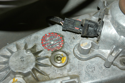
1: The New Process/New Venture type 231 transfer case is identified by its distinct I.D. plate. The 231 is popular on the Jeep YJ Wrangler, Jeep TJ Wrangler, the Jeep XJ Cherokee and some Jeep Grand Cherokee models. Read the plate carefully for details on type and application.
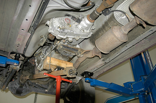
2: This ’99 Jeep XJ Cherokee features the NV231 transfer case coupled to an AW-4 automatic transmission. The Aisin-Warner automatic transmission has a proven track record for durability plus a versatile 4th gear overdrive. The AW-4 is only used in the XJ Cherokee and MJ Comanche models. NP231 or NV 231 usage includes YJ and TJ Jeep Wranglers and some Jeep Grand Cherokees.
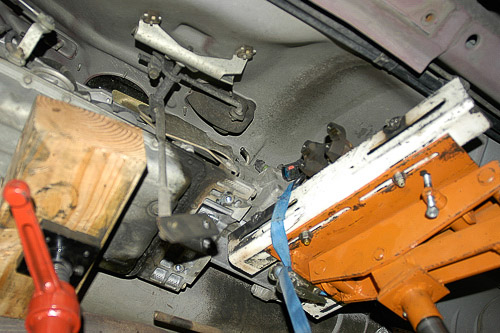
3: Drain fluid from the transfer case before removal. When removing the transfer case, cover the transmission output shaft and seal area to prevent contamination. Avoid binding as you slide the case rearward.

4: I use a transmission jack that provides careful tilting and protects the transmission and transfer case during removal and installation. Note the long, splined output shaft. This is the shaft that accommodates a slip coupler. The long shaft and slip coupler extend the overall length of the powertrain.

5: This is the only way to prevent damage to the aluminum cases and flanges: Use a transmission jack!
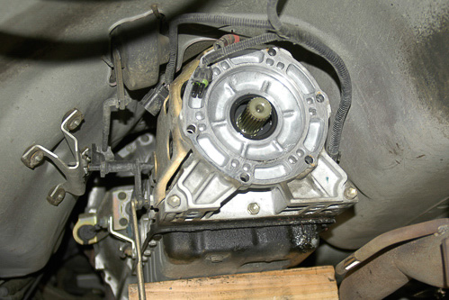
6: Prevent contaminants from entering the rear of the transmission. Place a lint-free rag or plastic cover over the output of the transmission while servicing the transfer case on the bench. An automatic transmission is high sensitive to contaminant damage!
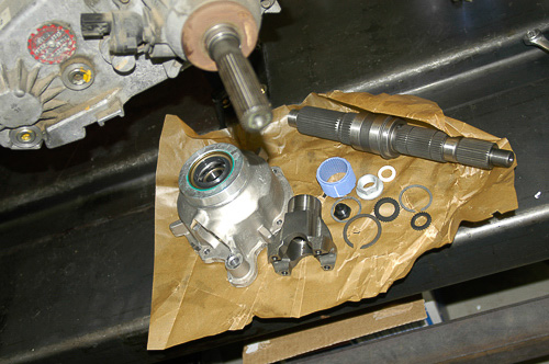
7: These are the Advance Adapters’ Fixed-Yoke Kit’s components. They readily match OEM quality castings, shafts and machining. The new output shaft is massive, providing 50% more stamina to better handle oversized tires, high torque loads and a chassis lift with steeper driveline angles.
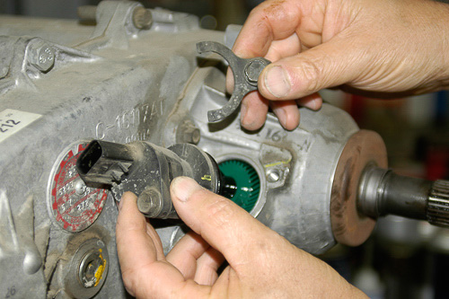
8: Mark the speedometer housing and clamp position before removing these parts. This electronic speed sensor unit still uses a conventional drive/driven gear mechanism on a ’99 Jeep XJ Cherokee. ‘SYE’ kit comes with a new output shaft drive gear that works with this unit. I mark the location of the clamp and housing for reassembly later.
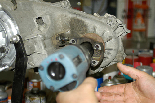
9: The stock front yoke nut comes off readily with an impact gun and 1-1/8” deep impact socket. You can hold the yoke with a large pipe wrench or special holding tool. Use of air impact force requires nothing more than light holding pressure to prevent the yoke from rotating as you remove the nut. Use impact sockets for this kind of work.
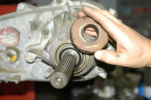
10: When installing an SYE kit, the slinger stop spacer will not be reused. If rebuilding the transfer case “stock,” protect the slinger and use the recommended puller.
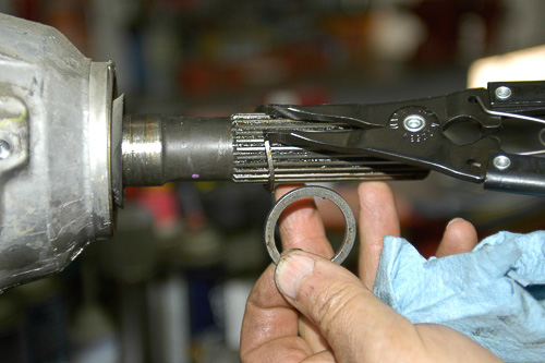
11: This is the first snap ring to remove. I use quality snap ring pliers to prevent distortion of rings during removal and installation. The Advance Adapters kit includes new snap rings to replace originals.
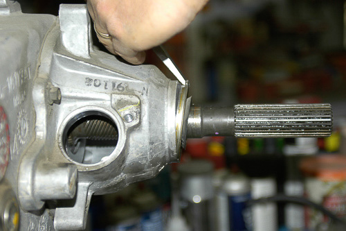
12: Remove the tailhousing/retainer seal with a suitable puller or by tapping at the seal’s outermost edge while staying clear of the aluminum retainer material. The rear retainer tail-housing is aluminum and will not tolerate prying with screwdrivers or awls. Always protect the aluminum castings.

13: Use an eye-type snap ring tool for this snap ring. This internal snap ring requires a heavy-duty tool designed for internal snap rings. Use the correct tool to prevent parts damage or physical injury.
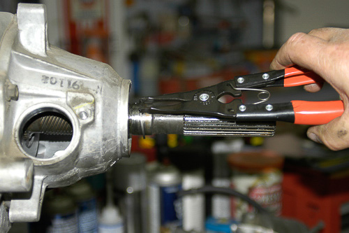
14: Removing this snap ring at the output bearing enables removal of the tailhousing-retainer. Slide the snap ring free of the output shaft splines.
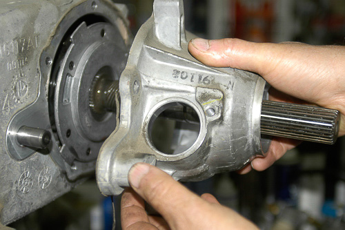
15: Remove the five bolts holding the housing in place. When separating castings, pry only at the factory prying points or the pry slots provided. If all hardware is loose, there should be no resistance beyond the sealant.
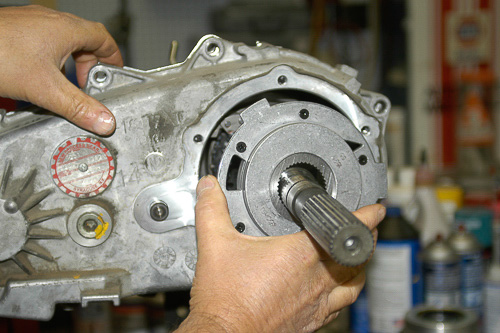
16: With the tailhousing removed, the oil pump is accessible. I slide the pump rearward, carefully, to disengage the oil pump tube from the pump unit. Tilting the pump will detach it from the tube inside the rear case housing.
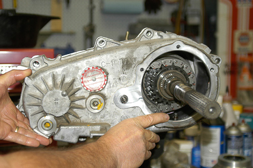
17: Remove the case bolts and note their positions. The bolts with washers go to the dowel locations. Keep track of hardware. When prying the case apart, look for screwdriver slots at opposite ends of the case. These serve as pry points. Use only these points and pry evenly, end-to-end. You are separating the sticking adhesive sealant.

18: Once you separate the case halves, you can see the oil pump feed tube and oil filter assembly. Use of an oil pump and filter is a higher-tech design. Clean the filter carefully during the rebuild process.
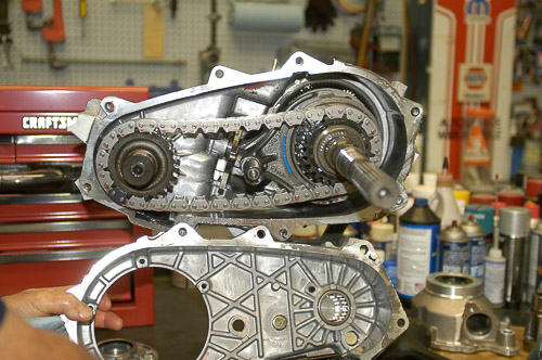
19: The front drive sprocket should slide out of its support bearing with light pressure. I use a plastic hammer, if necessary, to lightly tap on the threaded end of the shaft. There should be little resistance.
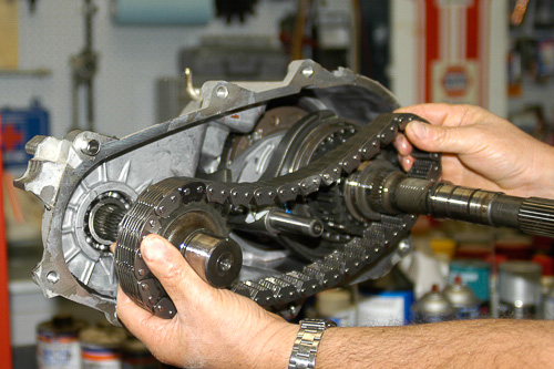
20: Once the front drive shaft is free of its bearing, the slack in the chain will permit removal of the chain from the output shaft sprocket. Do not force any of these parts. The NP/NV 231 is a precise, close-tolerance assembly.

21: You now have access to the main drive assembly. The shaft and drive sprocket will separate from the case as an assembly. Include the shift fork and shaft.

22: Output shaft and shift fork with rail are now removed from the planetary gearset. Note the relationship and fit of the outer shift sleeve and hub. Unless you have a damaged planetary, this is the extent of disassembly required to install the Advance Adapters ‘SYE’ kit. Advance Adapters provides thorough details and instructions.
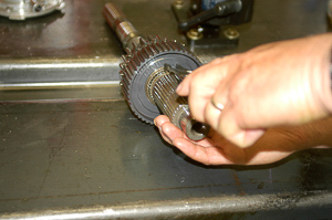
23: Sprocket removal from the output shaft begins with snap ring removal. Invest in quality snap ring pliers if you plan to do this kind of work regularly. Simply removing the snap ring will free the mode hub and sprocket from the original output shaft. You will not reuse this shaft, and a new snap ring is furnished with the Advance Adapters kit.
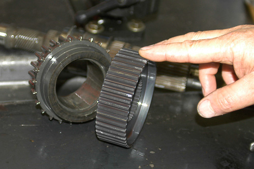
24: Inspect the drive sprocket, mode hub, shift fork and shifter rail for damage or excessive wear. Forced shifts and abuse of the transfer case are the most common causes of damage. These parts are rugged. The chain is a more common wear item, and even the NP/NV231 chain lasts a long time.
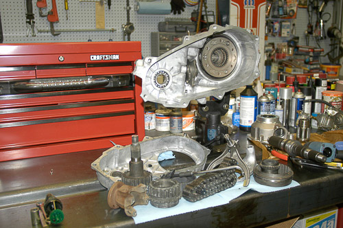
25: All parts except the electronic speedometer drive (speed sensor) assembly and electrical switches have now gone through the parts washing cabinet. Inspect parts carefully for damage. This is the time to repair or restore pieces, while the unit is apart on the bench.
